Have you used input biffer emiters as probe or anything else?peranders said:anli, I did some simulations with my diamond buffer only. I get a _very_ small difference when I have the input transistors conencted to the output vs. to +-15 volts.
With 1 volt in the difference is _very_, _very_ small and with 5 volts it's one dB or so.
For my cited amp
- +/-7.5V, 20KHz input signal,
- signal Rout is 7K5,
- PS is +/-17V,
2d and 3d sim-calculated harmonics at the emiters are
-75db, -79db - collectors are at PS lines,
- 107db, -123db - collectors are connected as I have suggested.
peranders said:My simulation frequency was 20 kHz but I think your circuit is more sensitive and maybe gain more with your feedback from the output.
Remember that I use transistors with Hfe > 450.
1. Input buffer is beyond the NFB loop!
2. Of course, sims/models differences may take place.
I have got the pcb's now and will build the prototype as soon as I got the time. It will be exciting to see if it works because it's directly from my brain via the computer. It may work, it may not but I'm rather convinced that it will ")
The pcb has groundplane on the "solderside". The design can be built for 115 VAC also There are jumpers on the "solderside" under the transformer.
Every time I'll do something with surface mountred parts I hear complaints but:
1 This isn't so hard to solder as you think. I have no problems to solder it by hand. 0805 parts are big....
2 SMD is cool and I like it:
The pcb has groundplane on the "solderside". The design can be built for 115 VAC also
There are jumpers on the "solderside" under the transformer. An externally hosted image should be here but it was not working when we last tested it.
Every time I'll do something with surface mountred parts I hear complaints but:
1 This isn't so hard to solder as you think. I have no problems to solder it by hand. 0805 parts are big....
2 SMD is cool and I like it:

Hi Per-Anders
I would like to thank you for your work on QRV_06, which I like very much. I was inspirated by it when I created my head phones amplifier. I´m sorry that I didn´t buy your PCB, but I wanted to use output transistors in package TO126 and I wanted to higher current to class A for 30ohm load. I also used connection DC servo, but I connected output behind input capacitor and resistance. I used for each solder two stages of filtration source vith RC members (separately for input buffer and amplifying stage).
Regards,
Bohdan

I can't wait to test the amp. It's cleaned, looks nice, not smoking, the LED's are emitting red light.... I wonder if janneman's theory in his sig will be comfirmed? I have made a TPA6120 current feedback amp which I really like but this discrete amp will I probably like more despite less good performance. It's hard to beat 1300 V/us with discrete parts for a couple of cents. The unique thing is that noone has made this combination before and certainly not with super regulators.
Is it possible to build? Yes, only if you are extremely thourough. Put all parts in the right places only. I succeeded with this but it's easier for me since I "know" the pcb. The amp is really tight and the designators are really small so you must be very carefull when you mount parts.
Anyway, you should see it built.
I'll hope I can test it next week.
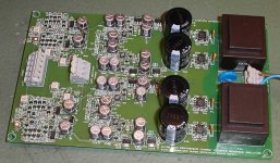
It's alive now and it worked right away, nothing added, removed or trimmed.
Pure discrete current feedback fed from a dual mono supply with quadruple super regulators. This is the first discrete SMD current feedback headphone amp in the world! and also the first headphone amp with integrated super regulators.
I'm very pleased and also happy and it's a good way of ending this day.
How does it sound? I'm quite happy with the results.
Pure discrete current feedback fed from a dual mono supply with quadruple super regulators. This is the first discrete SMD current feedback headphone amp in the world!
and also the first headphone amp with integrated super regulators.I'm very pleased and also happy and it's a good way of ending this day.
How does it sound? I'm quite happy with the results.
A better picture
I have taken a better picture.
I have taken a better picture.
An externally hosted image should be here but it was not working when we last tested it.
peranders said:A picture.... what do you think?
I Liked the:
" Ultra high performance current feedback headphone amplifier with snuberized super power supply "
LOL

I see that I must name mine " GT Turbo high rev intercooler ultra high performance.... "
hehehehehe
joke
It looks very nice, Peranders
- Status
- This old topic is closed. If you want to reopen this topic, contact a moderator using the "Report Post" button.
- Home
- Amplifiers
- Headphone Systems
- Current feedback headphone amp