It is supposed to improve PSRR. Edmund uses a similar technique in his Super TIS. It conserves the rail-modulated currents through the 150k resistors, and combines them so they cancel. I seem to recall that in the original configuration, asymmetric rail variations would cause higher PSRR than normal. Forcing the 150k resistor current to flow through both loops caused asymmetric PSRR to improve. But I also seem to recall there were some innocent gaffes made on that part of the circuit that got corrected later.
Edmond abandoned the scheme later on and I see the reason why.
Edmond abandoned the scheme later on and I see the reason why.
Will you say why?
THD offcourse, just as I predicted, see page 4 of his thread, he found another way of increasing PSRR though, see his latest schematic on his website. His search though was for better PSRR and found better THD instead by rather using classical super pair arrangement. I must see how well this other scheme works.
THD offcourse, just as I predicted, see page 4 of his thread, he found another way of increasing PSRR though, see his latest schematic on his website. His search though was for better PSRR and found better THD instead by rather using classical super pair arrangement. I must see how well this other scheme works.
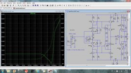
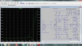
I simulated with different values of the resistor connected between Q9 and Q10 emitters and there is no significant change in THD or PSRR, so I stick with circuit as it was with Baxandall super pairs. I have Dimitry Danyuk enhaced cascode, but I think it could not be implemented here.
dado
The BC182/212 look like clones of the BC5xx series. They have Vce of 50V which is 5V better than the BC560/550. It looks like they were obsoleted by the BC556C/546C? But aside from the low Vce they appear to be as good as any BC5xx.
John Linsley Hood used them regularly.
I simulated with different values of the resistor connected between Q9 and Q10 emitters and there is no significant change in THD or PSRR, so I stick with circuit as it was with Baxandall super pairs. I have Dimitry Danyuk enhaced cascode, but I think it could not be implemented here.
dado
In your case might be insignificant althouh Im betting on that with resistor between the two emitters there is a definite drop in THD however small. In my case with a power amp where a high power outputstage must be driven the THD is nearly 25 % worse off for the crosscoupling. Even Edmond had a useful reduction in THD. The action that makes a super pair so linear is somewhat negated by the action of the cross coupling. Classical Baxandall super pairs dont use cross coupling. When I have some time Ill look at the scheme later adopted by Edmond.
In your case might be insignificant althouh Im betting on that with resistor between the two emitters there is a definite drop in THD however small. In my case with a power amp where a high power outputstage must be driven the THD is nearly 25 % worse off for the crosscoupling. Even Edmond had a useful reduction in THD. The action that makes a super pair so linear is somewhat negated by the action of the cross coupling. Classical Baxandall super pairs dont use cross coupling. When I have some time Ill look at the scheme later adopted by Edmond.
I simulated only current conveyor part, without output buffer, with cross connected resistors and resistor connected between emitters. I could get very insignificant drop of THD20k from 2.05 ppm to 2.02ppm but in that case the resistor was 4.7 kohm and dissipated 0.9 W(with 13 mA). One side effect was that power dissipation on Q6 and Q8 droped to 100 mW and low power transistor could be used. I am not sure if this is better.
dado
Happy New Year 2 all !!
And is there a CMR # for the circuit?
I am not sure how to simulate it with this circuit as here is only one input, maybe you can help me with it?
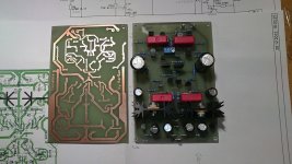
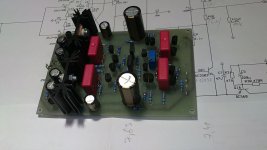
I have one channel working now, and preparing second one.
Damir
Attachments
At R9 would be a (-) input port to use for cmr tests.
Thanks, I will do that.
Here are some photos of the GainWire boards.
Attachments
Put the second AC source in series with R9. By bypassing R9 your circuit is running at full gain. CMRR will be higher at a normal gain.
I've got lower!
Attachments
Maybe true for modular instrumentation amplifiers but this circuit will only be connected one way in one circuit. It has passed all the requirements so far so even if CMRR is low, there may be little to gain from increasing it with this particular implementation.
R7/R8 give the + input slightly extra gain. At a current gain of 18.54k at the Jfet sources, this calculates to a CMRR of 2.85db, which seems to agree with the simulation. R7/R8 need to be bootstrapped to the negative input or replaced with current sources.
I think in the first simulation since you bypassed the 1k resistor you caused major offset which saturated/clipped the output resulting in optimistic PSRR.
- Status
- This old topic is closed. If you want to reopen this topic, contact a moderator using the "Report Post" button.
- Home
- Source & Line
- Analog Line Level
- Current conveyor as a voltage amplifier