Hi, got my transformer today but seem to be having a wierd issue, plugged my tranny up and powered the psu board for the Dac on to check voltages and im getting 5v on the 5v rail, +12v on the +12v rail but -14.7v on the -12v rail.
Any ideas as to what could be causing this, i dont want to plug the DAC board up untill i get it sorted.
Any ideas as to what could be causing this, i dont want to plug the DAC board up untill i get it sorted.
No shorts as of i can see, tranny is a 15v but is putting out 17, looks like im gonna have to grab another regulator!
Just looking through maplins catalogue, the regulator in the dac board is a l7912cv, is it replacable with any of these.
http://www.maplin.co.uk/Module.aspx?ModuleNo=31737&criteria=regulator negative&doy=20m8
Just looking through maplins catalogue, the regulator in the dac board is a l7912cv, is it replacable with any of these.
http://www.maplin.co.uk/Module.aspx?ModuleNo=31737&criteria=regulator negative&doy=20m8
Hi
Late on Tuesday night...
Whilst listening to the DAC last night one of the temporary solder connections attaching the right channel lead to the coupling cap broke away.
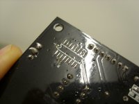
I re-soldered the lead and at the same time decided to remove the two blobs of solder from the chip on the base of the board. I fired it up again and only the left channel works. All of the connections seem fine and both channels from my amp operate ok via a DAC MAGIC2 box.
I re-soldered the two blobs next to the chip and now the output is very quiet and extremely distorted.
This is not a good way to finish the evening!
Wednesday night
Well...I have removed quite a number of the components previously added but am no further forward with regards to sound, still very distorted.
When I desoldered the small blobs from the base of the board next to the chip I think I may have damaged the solder pads (Solder is not sticking any more and they are barely visible).
Last night
I have checked all of he solder joints and I cant see bridging. I also checked the Digital voltage from the CS8416 and I am getting a reading of 3.33v on pin 23 and 21. I also have a reading of 13.24v from pins 4 and 8 on the opamp.
After considering my options I decided to remove the chip from the base of the board.
Can anyone advise which pads I need to short for bypass?
Thanks in advance
Richard
Late on Tuesday night...
Whilst listening to the DAC last night one of the temporary solder connections attaching the right channel lead to the coupling cap broke away.
I re-soldered the lead and at the same time decided to remove the two blobs of solder from the chip on the base of the board. I fired it up again and only the left channel works. All of the connections seem fine and both channels from my amp operate ok via a DAC MAGIC2 box.
I re-soldered the two blobs next to the chip and now the output is very quiet and extremely distorted.
This is not a good way to finish the evening!
Wednesday night
Well...I have removed quite a number of the components previously added but am no further forward with regards to sound, still very distorted.
When I desoldered the small blobs from the base of the board next to the chip I think I may have damaged the solder pads (Solder is not sticking any more and they are barely visible).
Last night
I have checked all of he solder joints and I cant see bridging. I also checked the Digital voltage from the CS8416 and I am getting a reading of 3.33v on pin 23 and 21. I also have a reading of 13.24v from pins 4 and 8 on the opamp.
After considering my options I decided to remove the chip from the base of the board.
Can anyone advise which pads I need to short for bypass?
Thanks in advance
Richard
Attachments
1-15 for left and 3-4 for right I believe, see:
http://theartofsound.net/forum/showthread.php?t=315&page=11
Iain
http://theartofsound.net/forum/showthread.php?t=315&page=11
Iain
iihay said:1-15 for left and 3-4 for right I believe, see:
http://theartofsound.net/forum/showthread.php?t=315&page=11
Iain
Hi Iain
Thanks for the info. I don’t know how many times I must I have read that thread!
I will give it a go latter
Richard
YES!
I've just soldered the the link in the past five minutes. The sound is back albeit only the right channel, and its not distorted. It is however sadly lacking in the bass department. Progress!
I have checked the connection between pin one of the opamp to the left output pin and its fine. I attached the meter to the right output pin but could not make a connection with any of the other opamp pins. I do have a connection between the blob on the base of the board and the right output.
I have tested the leads to the rca sockets and they appear fine.
Any suggestions?
Richard
 [/IMG]

I've just soldered the the link in the past five minutes. The sound is back albeit only the right channel, and its not distorted. It is however sadly lacking in the bass department. Progress!
I have checked the connection between pin one of the opamp to the left output pin and its fine. I attached the meter to the right output pin but could not make a connection with any of the other opamp pins. I do have a connection between the blob on the base of the board and the right output.
I have tested the leads to the rca sockets and they appear fine.
Any suggestions?
Richard
I meant the left channel is working, not right.
I have put a meter between pin 1 of opamp and L-OUT and its fine. But I don't get a reading between pin 7 on the opamp and R-OUT. If I turn up the volume on the amp and turn the balance control right around I can hear I faint sound (Probably cross-talk)
Completely stumped
HELP.....Please
I have put a meter between pin 1 of opamp and L-OUT and its fine. But I don't get a reading between pin 7 on the opamp and R-OUT. If I turn up the volume on the amp and turn the balance control right around I can hear I faint sound (Probably cross-talk)
Completely stumped
HELP.....Please
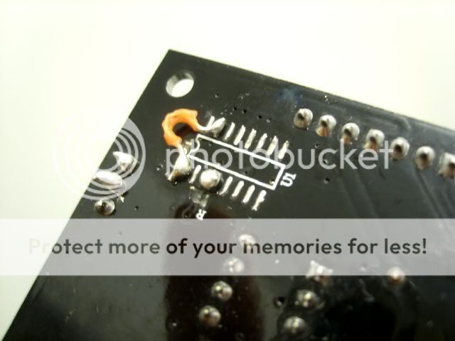
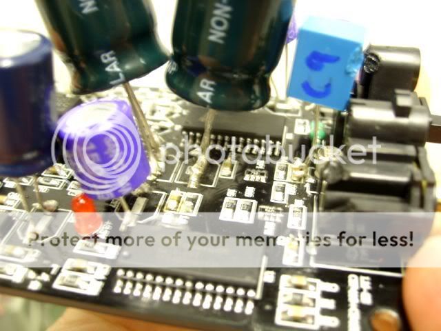
kanifee said:dont know how relavent this is or weather it makes a differance but is that a short in the picture marked with the red line?

do you also have an opamp from another device to test in it?
Hi Kanifee
Thanks for the reply.
Its not a short. I have managed to sort the problem.
You can read the story below
http://theartofsound.net/forum/showthread.php?t=315&page=20
Hi
I have been playing with one of these boards and have followed this thread http://theartofsound.net/forum/showthread.php?t=315
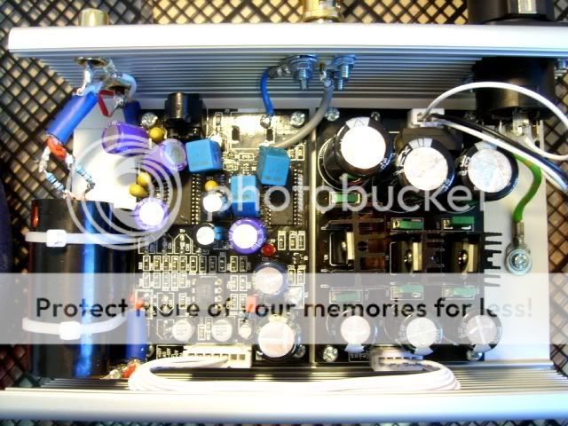
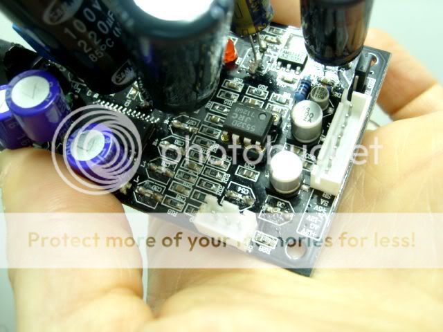
Here is a list of the components changed so far...
C3 Jamicon 220uf
C18 Jamicon 220uf
C11 3.3uf Tant
C10 Vishay 0.1uf ERO 1837
C7 Vishay 0.1uf ERO 1837
C9 Vishay 0.1uf ERO 1837
C16 Oscon 150uf
C8 3.3uf Tant
C12 3.3uf Tant
C25 Oscon 150uf
C26 Oscon 150uf
C13 3.3uf Tant
C41 Wima 0.1uf
C19 Panasonic FC 2200uf
C21 Panasonic FC 470uf
C17 Oscon 150uf
Bypass caps are SCR 8uf with R68 resistors
Using standard JRC opamp and have also tried LM4562
The output sounds a little bit veiled and lacking sparkle. The internal coax is a 50ohm cable from Maplin. I was after 75ohm to match the 75ohm socket but the chap at Maplins said it would not make any difference because the cable length was so short.
I have been running this for a while and the bass is still poor. I don't like a really pronounced bass but after listening to a variety of music it is obviously lacking.
Can anyone provide a suggestion?
Thanks
Richard
I have been playing with one of these boards and have followed this thread http://theartofsound.net/forum/showthread.php?t=315
Here is a list of the components changed so far...
C3 Jamicon 220uf
C18 Jamicon 220uf
C11 3.3uf Tant
C10 Vishay 0.1uf ERO 1837
C7 Vishay 0.1uf ERO 1837
C9 Vishay 0.1uf ERO 1837
C16 Oscon 150uf
C8 3.3uf Tant
C12 3.3uf Tant
C25 Oscon 150uf
C26 Oscon 150uf
C13 3.3uf Tant
C41 Wima 0.1uf
C19 Panasonic FC 2200uf
C21 Panasonic FC 470uf
C17 Oscon 150uf
Bypass caps are SCR 8uf with R68 resistors
Using standard JRC opamp and have also tried LM4562
The output sounds a little bit veiled and lacking sparkle. The internal coax is a 50ohm cable from Maplin. I was after 75ohm to match the 75ohm socket but the chap at Maplins said it would not make any difference because the cable length was so short.
I have been running this for a while and the bass is still poor. I don't like a really pronounced bass but after listening to a variety of music it is obviously lacking.
Can anyone provide a suggestion?
Thanks
Richard
Puffin said:Suggestion: It's shagged mate, send it to me !
I used a combination of (shriek!) wirewound resistors on the input, 2x22ohm, 2x100ohm and others! (mine is a balanced input)
Sounds absolutely fabulous
If I were you I would try using the pads at C27 and C30 for the input.
Puffy, thanks for the offer but I would like to try and resolve the problem. I'm sure its nothing too serious as it sounds OK apart from the bass.
Tripmaster Trip
Back at post 27 the recommended traffo was 50VA and 15/16V secondaries.
I've just got a bargain traffo (brand new) for £0.82 (yep, £0.82!!) which is 60VA and 2 x 15V torroidal. I assume this will be fine for the DAC - maybe a little overkill for the primary VA, but the secondary outputs are in the 15-16V range.
Traffo was from CPC Farnell and was under their Special Offer/Bargain component tab from the main website.
jonners said:It works fine at 44 and 48kHz, but at 96kHz I just get a hissy noise. I consulted the Cirrus Logic CS4397 data sheet (bit out of my depth here, to be honest) and found that the mode operation settings on this board, which are M0=1 M1=0 M2=1 M3=1 M4=0, give 'single speed' (16 to 50kHz) I2S operation at up to 24bit. However, according to the data sheet for the Crystal CDB4396/7 Evaluation Board, these same settings give "Automatic Mode Operation'.
[/B]
I am trying to pipe the I2S from my CD PRO 2 direct to the CS4397. After reading the datasheet, I see that M0=1 M1=0 M2=1 M3=1 M4=0, give 'single speed' (16 to 50kHz) I2S operation at up to 24bit. Which means this mode will also be able to accept the I2S from the CD PRO 2 which is running at 16bit right?
Thanks for any help...
ED
Best results
Hello to all,
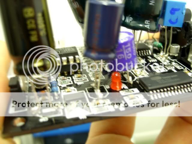
I played with this board for some time. Change components, replace OPAMP with 2111, but THE best results is if you solder left and right chanels directly on DAC schip (there are 4 caps after chip and before output stage. On first connectr one chanel, and on last one connect another chanell. There should be 2 caps between these two connections.
So whole output stage together with OPAMP i trashed
Chears
Hello to all,
I played with this board for some time. Change components, replace OPAMP with 2111, but THE best results is if you solder left and right chanels directly on DAC schip (there are 4 caps after chip and before output stage. On first connectr one chanel, and on last one connect another chanell. There should be 2 caps between these two connections.
So whole output stage together with OPAMP i trashed
Chears
Really make the DAC Sing
If you really want to hear this DAC perform, try an output transformer. Any high quality 600:600 line level transformer will work. I have been using a UTC A-20 500:500 and it's breathtaking. I am not alone. See this thread for more details.
http://www.diyaudio.com/forums/showthread.php?s=&threadid=137976&perpage=25&pagenumber=1
Ciao
- Status
- This old topic is closed. If you want to reopen this topic, contact a moderator using the "Report Post" button.
- Home
- Source & Line
- Digital Line Level
- CS8416/CS4397 board at 96kHZ?