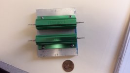
finished up resistive load and hooked up to amp channel 1. Power up and the bulb stayed glowing.
measured 7.8V on channel 1 speaker terminals DC state
channel 1 pos rail 9.36V 0 state
channel 1 neg rail -9.82V 0 state
Vbe pos output transistor .66V DC state
Vbe pos driver .65V DC state
bias setting .73V DC state
pos output transistor emitter resistor 69mV DC state
Vbe neg output transistor 0V DC state
Vbe neg driver 0V DC state
Bias setting. 0V DC state
Vbe pos predriver .67V DC state
pos predriver collector 9.38V 0 state
pos predriver emitter 10.01V 0 state
pos predriver base 9.32 0 state
Vbe neg predriver 1.69V DC state
neg predriver collector 9.83V DC state
neg predriver emitter 7.84V DC state
neg predriver base 9.56V DC state
Last edited:
Amp S/N 28945
DCA board #9785
IOC board #9794
Output boards #7954
The schematic MI 250D DC300A Series II. It states on this schematic that it applies to main DCA board #9785 and IOC board #9794.
Has me wondering if the DCA board and IOC board have been transplanted from a DC300A seriesII.
Anyone have experience with the board #'s and product line?
If the negative predriver you took the measurements on post 102 is Q107 which is PNP, then either there is a bad solder joint or the transistor is bad. You can't get 1.69 v forwards on a base-emitter junction of a pnp silicon transistor unless there is a rediculous current going into the base. You can measure the current across R130.
You can measure for a bad solder joint by measuring the voltage between the lead and the pad. I use a Pamona grabber on the lead. You can also measure voltage to the other end of the trace (R130) to see if it is burned through or something.
I got nothing on the schematics you e-mailed yesterday but an outline on a black screen, but a reboot today seems to make them display.
My amp works fine with the room heater in series with the AC line up to several watts, I don't know what is so special about a DC300. As long as the op amp rails are up to voltage and the rails are twice the output voltage.
Last edited:
indianajo, djk was correct in having the light bulb removed while operating the amp with any type of load. The measurements in post 102 were taken when the amp had the light bulb on it and was powered on with a load. In that scenario I believe some of the transistors latch one way or another and would stay that way similarly as was seen when the amp was powered on using the variac. Once again thanks djk for monitoring my efforts. Those measurements taken in post 102 were with the light bulb in place and a load on the output. Those measurements would not be measurements taken on an amp that one would think was capable of playing music? And as stated in previous posts the reworked channel 1 has been hooked up several times and found to be operable.
Last night removed bulb and powered amp up with resistor load. Did not see the same issue the amp was having on power up with a resistor load on it (DC of 7V on output). The max'd out 200ohm trimmer was still in place so the bias setting on channel 1 was still over 400mV.
This morning I took 3ea 100ohm resistors in series and replaced the trimmer. I wanted to convince myself that the bias was capable of being adjusted. This scenario dropped the bias below the 315mV minimum allowed, good news. Next step is to get the select bias resistor/s that work and get them in place.
Then another round of measurements without the bulb in place. thanks to everyone this amp might come alive.......
The main PS rails were reading 44V instead of 60V because the light bulb was in place. Without the light bulb the rails are measuring 63V. So the comment I made about rms and p-p voltage was incorrect (Post #39).
In a hold pattern. A 270 ohm bias resistor should be delivered tomorrow. This should get the bias for channel 1 in spec. I have been thinking that since the opamp output is low, if it is increased that it might impact the bias as well?
Anyways bias resistor will be installed. I think the next step is to put the audio generator and oscope that was purchsed to work. Definately will be looking forward to support on this.
Will use the resistive load fabricated. Will input a sinewave of what freq. and amplitude?
Will start with looking at signal at input of opamp and at output?
Last edited:
looking at opamp input, the input signal immediately is squashed by the 25K linear potentiometer(gain adjust). Using a line out from a portable CD player for an input signal it doesnt appear to be much of a signal when measured across the jack itself (signal jumps around ±10mV). Then I quickly came to the realization that with the gain adjust fully counter clock wise no input signal is fed to the opamp (the signal hits 25K of resistance). Am aware of the line level difference between these portable players and a dedicated home audio
input signal generator(cd player, etc).
This got me interested in the opamp output +1.35V required at idle? This measurement is made with no input signal being plugged in to the amp? The gain pot turned fully ccw. If this is the case then the circuitry to the - inverting input has to deliver the signal to the ± opamp input signal inputs?
I ask because on this amp there is 5.1mV at +in A and 5.6mV at -in A and 0.0mV at -in B and -0.7mV at +in B with no iput signal fed to the amp. So the feedback loops supply the small signal to the - inverting inputs of the opamps? Both channel 1 and 2 opamp outputs are similar -.3V.
just noticed it is not just the feedback loop but more likely the output offset pot that supplys the neg. input invert signal pin 6 to the opamp?
this circuit is between the +10V opamp rail and the -62V PS rail. there is a 3.3k resistor in series with the 100k output offset pot.
will measure V (0 state) at the opamp end of R106 (820K) this must determine the voltage at pin 6 neg invert input? the feedback loop ties in there as well.
one would assume adjusting the output offset pot R105 would change this value?
This DC300a amp is specified to perform down to DC- that is if you put 20 mv into it, what ever gain you have the pot set to (say 20) it should put out .4 v DC. See paragraph 1.
That means that they have to "null out" the DC offset of the op amp to achieve this. Op amps don't typically put out 0 v with (.0 -0 ) v in, they put out something else. That is why your op amp has more than two inputs and one output, it has the nulling inputs. I never downloaded the spec sheet for your op amp because my amps do not go down to DC and I am never going to find one of these op amps in a music or PA amp. I suggest you do download the datasheet on the op amp and look at the names of the inputs and what suggestions they have in the application notes for a nulling circuit.
Your amp has both 1. input DC nulling pots, and 2. output nulling pots. Some source signals do produce DC, for example my RA88a mixer put out 2.5 VDC pretty freely on the CD/radio inputs. Totally screwed me up trying to drive it with a home built sine wave generator until I figured it out.
As said earlier, the definition of op amp, means the gain is fixed at A*(v+ -v-) where v+ is pin 5 and v- is pin 6. A=(Ri/Rf)+1. I think Ri is R102 (1k it says) plus whatever you have the pot R100 set to, and Rf is 180 k. I could be wrong, I'm not the world's biggest expert on op amps.
So anyway, if they told to to turn down the input R100 to CCW when nulling the output DC level, that is like shorting the input (which give is no signal).
Then the op amp has more gain than you need, and the AC signal is attenuated by R100 pot to where you get the signal out that you need. The gain of the op amp or the rest is not further adjusted for volume.
BTW, most music amps use 3 pin op amps with no DC nulling feature, and only work down to 20 hz or so because nobody hears below that. Some pricey PA amps have DC coupled op amps for the input with a feedback circuit doing the DC offset nulling, because "no caps in the signal flow" is a big sales point for some people. But most music amps have a capacitor on the input and or output to block the op amp DC offset voltage and ignore it.
I still don't know if R101is a 2 meg resistor or not. If it is then the offset nulling pot doesn't affect the gain much. But if R101 is not 2 meg (I can't read any of these prints that well) then the Amp factor "A" is affected by the input null DC voltage because the input resistance is the parallel resistance of all the resistors attached to the input. 2 meg ohm parallel 10k is about 10k.
When you are testing your amp for music production, obviously you need to turn the input pot R100 up to have a detectable AC signal out of the op amp.
The reason Crown set the idle voltage of the op amp to 1.35 has to do with how many silicon junctions they have to compensate for between op amp and output, and I'm not going to count them, it is too complicated for me. Just having the output DC idle current come from one pair of transistors and all the other ones operate class B is pretty weird. No wonder you couldn't run it with the light bulb on the input. My 100% class AB output amps, so far you can use any transformer AC input load that lets the op amps get up to power voltage.
BTW there are two "feedback" functions on this or other op amp driven amps. One feedback resistor, R149? sets the gain of the op amp (with the input resistance). There is another feedback resistor (or network) that takes the error of the output transistors back to the minus input of the op amp, to correct for the non-linearities of the later stages.
One spooky thing about using this amp for music, is that speakers don't like DC voltage, and if this amp is not perfectly rebuilt it may produce it. As the temperature varies the DC voltage out of the amp may vary outside the 10 mv specification. Now 300 mv of DC probably won't hurt your speaker, but 8v will. My PA amps have DC detection circuits, that are supposed to shut down the output to the speaker if there is any. This amp doesn't have one, that I can see.
Last edited:
thanks indianajo, yes as you know my forte is not electrical circuit design.
Resistor R101 is a 2Meg resistor.
But my thoughts are: if the ua739 is good that what is causing the low output of the opamp has to be common to both channels 1 and 2. Doesnt this reduce the possibilities?
Also want to ensure that the +1.35V opamp output measurement is being taken correctly. It is currently being measured with no load and idling (gain pot CCW).
I have decided to start replacing some of the voltage double circuit parts. I will start with D4, which I know has already been stated as a replace part. R3 2.7K 2W as well. Then replace aluminum electrolytic caps C4, C5, and C6. Any other suggestions would be appreciated...since an order will be placed with Mouser?
in general time sensitive transistor amp parts are
1. electrolytic capacitors. The rubber seal gets oxidized, then when warm the water can evaporate out. Rare "epoxy sealed" and "10000 hour" caps are probably not as sensitive to the years. I replace all e-caps on gear over 15 years old with problems, so does Sakis of East electronics.
2. Zener diodes and voltage regulators IC's that have a zener diode built in. Band gap reference (read datasheet) regulator IC's are not so time sensitive.
3. High value carbon comp resistors, those over 100 kohm particularly. Expecially ones built outside the US. Water gets in and *****s up the value, and there is some sort of partical migration feature, too. Resistors built on lines that sold Mil Spec parts to the US military (Allen Bradley, Sprague) have good paint post 1960 and are not sensitive to water IMHO if they don't look burned or bubbled. You can measure resistors pretty effectively.
4. Potentiometers and switches, especially ones used a lot like the volume and tone control pots. Pots with DC current on them are especially stressed.
5. Power semiconductors that go through huge thermal cycles. I don't replace these and have got away with it, but it kills old TV's frequently. Any transistor pre-1966? due to thermal stress on the die attach leads in plastic packages, but I don't think this amp is that old. 2n53xx is post 1975 anyway.
6. Fans.
So take your choice in replacing non-broken parts. R3 the 2 watt isn't on the parts list, so I don't know if it is carbon comp, wire wound, or something more exotic. Wire wound resistors are very long life from Ohmmite Dale and Vishay, the only design fault is the terminal weld on the end of some lesser brands.
I still haven't heard that you have minus to minus e-capacitors protecting your speakers from DC. You need this for debug anyway, and if I were you I'd leave them in permanently. They add a little distortion at high frequency, my tests have proved, especially on amps that pass through the 0 volt chemical event. (They sound fine if properly biased 1/3 rated voltage or above). Of the ones I've bought lately in the 3300 uf rating or above, I like the Panasonic ECO series. they are rated service life 3000 hours, ripple at end of life is as good as anybodies, ESR is okay, and they have been coming in made in USA. You need a voltage rating twice what the rail is, and I buy 4700 uf ones for speaker protection, which gives 2300 uf back to back which is okay for bass response on 8 ohm speakers. If I had 4 ohm speakers I'd buy 6800 ohm speaker protector caps.
Else build an active speaker protector circuit, which consumes entire long threads of diyaudio.com and has just consumed 2 winters on my PV-1.3k trying to build something that would actually work more than once.
If this amp has dual banana jacks, soldering your speaker wire to a dual banana plug prevents stray wires from shorting against the chassis in a live performance situation and blowing up the amp. Waay better than 1/4 phone plugs, which short every time they are pulled out a little bit.
Personally I'd like a uA739 IC or two in the parts box, they are weird and they won't make them forever. I don't believe you have done the math yet on U1 input versus output, or listened to music to prove your U1 is good yet.
And what are you going to do with this? If you're not driving an actuator that requires DC output, I'd be tempted to scrap the internal driver electronics, salvage the heatsinks, output transistors, pots fan and power supply and drive the O.T.'s with a pair of LM49810 IC's mounted on perf board. It has been a good learning experience, but this thing is way too complicated. My PV-1.3k is as complicated, but it has 4 x the power and isn't designed to put out DC voltage.
Last edited:
Prior to 198? parts in microfarad ranges were marked xx mf which meant xx microfarads.
Post 198? parts marked mf were in millifarad, so 10 mf now would be 10 millifarad or 10000 microfarad. These cost about $20 each and are the size of a small soda can.
If your amp was assembled prior to 198? then the part is probably 10 microfarad. You can tell from the dates on some parts 4 digits where the date is YYWW for the 1-53 week of 19YY.
that voltage rating or higher should be fine. On websites now like mouser, you are looking for a 10 uf cap, since the vendors have decided u is the same as a greek mu, which has a leading tail IMHO.
I've been following this thread since the beginning and it has renewed my interest in getting my beater DC300A up and running. Anyway, in the DC300A Series II with the UA739/749 "C3" is the negative filter capacitor in the power supply, 13000uf @ 70 Volts. "C4" is the 10uf/160v capacitor that feeds the voltage doubler on the main PCB, should be an axial type. C5, 10uf/50v, is the filter capacitor for the doubler.
Craig
Craig
thanks Craig
Initially I thought the DCA input board was a DC300A since the chassis is. But the board number is 9785. I believe this is out of a DC300A Series II. Most of the hard wiring has been touched supporting the comment that it must have been transplanted.
But you are right C3 in a Series II is one of the big PS caps. I am looking at some of the smaller al electrolytic caps in the voltage doubler circuit.
C4 10uF/150V
C5 and C6 have evidence of being changed already.
purchased a new/old ceramic package ua739. $12.00 delivered. From Ca. will be awhile before I can test it. Who wants to take odds on the difference in the opamp outputs?
Craig, the jacks for the chassis are all above the PS caps. It has the silver DC300A face. It is a DC300A chassis with a DC300A Series II DCA input board. I don't think that is a bad thing and am not aware of any reasons why it couldn't be done but heck what the hell do I know?
I have not given up the challenge to see if I can get the opamp outputs up above 0V...
But if both outputs are at the same -.3V level it has to be something in common to both channels?
I have not given up the challenge to see if I can get the opamp outputs up above 0V...
But if both outputs are at the same -.3V level it has to be something in common to both channels?
- Status
- This old topic is closed. If you want to reopen this topic, contact a moderator using the "Report Post" button.
- Home
- Amplifiers
- Solid State
- Crown DC300A Repair/Restore