The speaker negative terminal, and various other points, is your ground terminal. Say the ground is the end of R146 where it connects to the 0.1 uf capacitor and the ground binder terminal. That is the main thing you could get wrong in measuring.
Your meter could also be out of calibration, with your 9.2 v versus 10, but you put new zener diodes in there, right? Did they come from a major distributor, ie new stock? I use B tolerance zener diodes from newark.com or mouser.com to calibrate my meter, which reads fine.
If you got the new zeners from a surplus house and they are out of tolerance, I'd let the -9.8 zener be but insert a 1n4148 line to line in series with the 9.2 to pull it up to 9.9 v.
Then I would use the offset adjustment pots to make the op amp output 1.35 like it says, then since your problem is with the resistor on the output, (speaker, but you put that away didn't you?) do that then trace the feedback path back to op amp in 6 (inverting input) to see if something is blown up in that path.
You can also track the op amp output to D10blob (collector of Q100) and D10blob (collector of Q104) where you have other voltages listed, to see if the voltages are correct with the op amp out at 1.35. Then check the D10blobs that they are dropping about 0.6 v, slightly turned on.
There are other voltages you can check at Q106 at the bottom and D3 at the top. Etc. You've got a layout, you may want to make a copy and write on the copy test points like A, B, C etc, which correspond to voltage points A, B, C, you write on your copy of the print.
Last edited:
indianajo are you suggesting not to use a negative speaker terminal output as the ground to make the volatge output measurements? After review closer ground references to the opamp were found, see attached.
The diodes have not been replaced but will be. thanks
The diodes have not been replaced but will be. thanks
Attachments
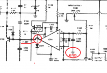
You can use the speaker ground terminal, but that gets in the way of the resistor you are plugging in to cause the DC offset problem. I gave you another covenient easy to find ground place inside the box, the connection between R146 and the 0.1 uf capacitor.
Usually putting alligator clips on IC's directly can cause shorting between pins and blowing up the IC. If you measure on a DIP IC directly, be sure to use Pamona DIP clips, and some Pamona grabbers. Using regular alligator clips to examine IC pins, I try to find an equivalent place on the board that has a regular isolated lead, like a resistor, capacitor, or diode. A scope probe ground doesn't have to be all that close at audio frequencies.
If the 9.2 v is original, yes definitely replace whatever zener is regulating that voltage. In passing check the resistor feeding that zener diode,that is is the marked value or lower.
And before I soldered in a new zener diode, I would put a suitable resistor in front of it and measure that the voltage is within 5% on a B suffix part, ie 9.5 v to 10.5 v. The test current on a 0.5 W zener 1n5240 is 20 ma, so using my DC supply of 17 v to test it, I would want the series resistor on the line end (plus to DC supply) to drop 7 volts to get the zener down to 10 v. So 7v/0.02 a=350 ohms, so I would use a 470 ohm or 390 ohm resistor to test the new zener diode voltage. It should also be a 1/2 watt or bigger resistor. I do this test with clip leads from Radio Shack.
My 17 v supply is a 12 v car battery charger (12 VCT transformer) with two rectifiers and a filter cap on it. Note modern IC controlled car battery chargers may not operate without a battery attached, or stop charge for some silly reason. You could use any other transformer-rectifer-filter cap arrangement if you change the voltage in the calculation above to find out what resistor you need to protect the zener diode. If you use a wall transformer ($1 at Salvation Army) for a DC supply, they usually have a big value internal resistor, so you have to load the wall transformer down with various resistances to find out what the resistance is internally. A wall transformer, also, at low current the DC voltage out is higher than the rating at the rated current.
Last edited:
finally found D4, the +10V zener. It was buried under a resistor. Discovered it by measuring every visible diode on the board and finally last night I noticed this diode in a very tight spot. when I look at the schematic it seems to me that there is more than one resistor involved in generating the current that runs through the diode. There are several resistors on the cathode end of D4. I will set up test of new diodes using 24VDC PS. I can use a 1 kohm resistor in front of the diode to generate 24mA. The resistor goes on the anode end? Then do I just measure the potential difference across the diode?
If I do this before I put it in the circuit then if it still reads low I know it is not the diode but other issues that need to be found.
I played with the pots for adjusting DC Balance and observed no change to the outputs of the opamps? Stayed at -.5V when it should be at +1.35V.
If I do this before I put it in the circuit then if it still reads low I know it is not the diode but other issues that need to be found.
I played with the pots for adjusting DC Balance and observed no change to the outputs of the opamps? Stayed at -.5V when it should be at +1.35V.
Doing zener test you can put the resistor on either end. I usually put it on the cathode end, the way plus regulator circuits do it. I couldn't spot on the schematic where the pin 14 and 7 were coming from, glad you found it on the layout. I can see the trace 14 going to D4 on the layout drawing p38 of the manual. It apparently is the bottom of the board because pin 1 is on the upper right. 14 isn't labeled but runs under the IC over to R20blob right next to D4.
I had two blown up op amps on each driver board, you may need to test. An op amp mathematically puts out A(input difference voltage)=output voltage. A the amplification factor is a big number. DC300 has a feedback resistor R149 100k? 180?, divided by (whatever R103 is +R101(20K?)) that is
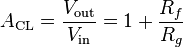 from wikipedia. I can't get rid of the bold. [/B]So you measure the resistance of the input offset pot, add to 20k, divide by R149 to get the gain, plus 1. Then power on you measure pin 5, 6, and 1. Vin=V5 minus V6. Vout is pin 1. If that equation doesn't work, IC1 is blown or something like Q100 or D100 or C108 or C105 is leaking more current than the op amp can handle (which is probably what would blow it up).
Good luck hunting the problems. One knows a whole lot more when one finishes one of these than he does at the start.
I had two blown up op amps on each driver board, you may need to test. An op amp mathematically puts out A(input difference voltage)=output voltage. A the amplification factor is a big number. DC300 has a feedback resistor R149 100k? 180?, divided by (whatever R103 is +R101(20K?)) that is
Good luck hunting the problems. One knows a whole lot more when one finishes one of these than he does at the start.
Yes, go to eserviceinfo.com, search on DC300a or crown, click on the right manual, then in the middle of the bottom there is a download now text that is not highlighted. Click on that to download the file. This gets you a pdf file for adobe reader. The schematics are worse than yours as the 8's 0's 6's and 9's all look alike, but the board layout is priceless.
replaced D4 zener on +10V. +9.2V increased to +9.5V.Output of opamp went from -.5 to -.4, below the +1.35. I took a bunch of measurements that have been recorded on a copy of the input board layout drawing. When I clean up the sheet will publish or email to you.
The +5V offset reference on the collector of Q1 measures +5.5 should be +5. The +2 required on the emitter of Q100 measures 0.18V on Channel 1 and 0.2V on channel 2 well below the required 2V(emitter Q100/200).
still interested in the + and - 60V rail measurements that I am getting. They measure closer to 44V. Is this a RMS measuremnt taken via the DVM while if measured with an oscope it would exhibit 60V peak to peak?
the bias on channel 1 is still too high.
put the 200ohm trimmer in place instead of the 150ohm hand select(channel 1). This is the channel that got all new output and driver transistors and the positive and negative predrivers on input board(Q106,Q107). With 150ohm hand select in place the bias channel 1 is 420mV. with the 200ohm trimmer max'd out the bias is at 357mV. I have the amp operating again. Channel 1 is operable. Will check to see if I still get the power up issue with load on the speaker terminals. Previously with the speaker left attached on power up the light bulb stayed glowing brightly and didnt dim. Currently I power up the amp and connect speaker after power up. Today I did power it up and shut it off with speaker connected and didnt see the same issue not sure if letting the caps drain fully might cause the power up issue. Yes it is still having the same issue....assume DC offset at power up with load on speaker terminals. I will get two 10 ohm 100W resistors tied together and use that instead of speaker.
Last edited:
I'm not worried about Q1 measuring 5.5 instead of 5.0. It only feeds voltage to two adjustment pots, so you should be able to compensate with the pots.
I am worried about -0.4 v out pin 1 of IC1. I would do the pin 6, 5, 1 measurement and calculation. Is is performing mathematically? then if IC1 is socketed, I would pull IC1 and see how much current is coming out of Q1. Then I would check that that current is within specified current load of a 739 or 749. If the IC is not socketed, I would pull the base of Q100 see if it passes a quality test at significant DC voltage. Of course if it fails the double diode test on the DVM, no reason to go on to voltage-current check. Also test D10blob, the diode between collector and base of Q100.
Two 10 ohm resistors tied together sounds like a suitable speaker simulation load.
Edit, cross posts, will look at your op amp results. The "bias current" is high, and you have only measured one side, not the other. There are 0.34 volt indications on both R132 and R139.
Edit 2, 5.1 mv -5.6 mv is -0.5 mv, and you are seeing -.4 v out, for a gain of 100? Is R101 a 2 megohm resistor? red black green? Is R149 a 180k resistor, brown grey yellow? If they are then the gain should be about 180k/11k or about 16 to 20.
Last edited:
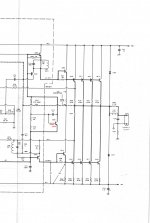
IC1 UA379 had a pin on leg 1 so that a probe could be connected to it. When I went to remove IC1, very carefully, I discovered that the leg of the chip was missing, the larger section of the leg adjacent to the chip was there, and the pin which I thought was soldered to leg 1 stayed in the socket. Thought maybe this was the problem with the output. I soldered the pin back on to IC1 leg 1 and reinstalled back in socket but no change in output. You were correct on your resistance values for R101 and R149 used in the calculation. On channel 1 the bias setting across R132 and R139 were high 420mV. Currently I replaced the hand select R129 with a 200ohm trimmer which is currently max'd out and the bias is measuring 360mV. The original hand select R129 was a150ohm resistor. So this has been increased to somewhere around 200ohms and the bias setting was reduced by 60mV.
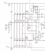
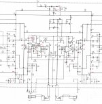
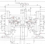
I have attached the channel 1 output board schematic with measurements taken to date. I will attach the other sections of the schematic with measurements today as well. Hopefully they are readable?
I have attached the channel 1 output board schematic with measurements taken to date. I will attach the other sections of the schematic with measurements today as well. Hopefully they are readable?
Attachments
Yes, I agree!
I have a DC300a Series II, and, It is not the same as a DC300a,
Also the DC300 was a completely different animal.
It appears the there is two versions of the DC300a II as well !!
Here is the link to all of the versions of service manuals direct from Crown,
Discontinued Amplifier Products
FWIW
jer")
P,S. Sorry, I didn't see that this was already posted very early in the thread.
I have a DC300a Series II, and, It is not the same as a DC300a,
Also the DC300 was a completely different animal.
It appears the there is two versions of the DC300a II as well !!
Here is the link to all of the versions of service manuals direct from Crown,
Discontinued Amplifier Products
FWIW
jer
P,S. Sorry, I didn't see that this was already posted very early in the thread.
Last edited:
5.5 v at D4 is very wrong. You may want to check both ends of all the load resistors to see which one is hogging the current. We already had evidence something was wrong with IC1, check if the resistors to it show it is the current hog. Also Q119.
Q104 has the base back biased if I read this right. I would think at idle no signal it would be slightly forward biased (.6v) to let a little idle current through the output transistor driver to eliminate crossover distortion.
I thought channel 2 was the one that was okay, I thought channel 1 was the one producing DC voltage with a load on it. ???
Have had a cold since Saterday afternoon. I'm not doing much thinking while I take diphenhydramine. Sorry
If you are going to prove that the emitter resistors have no current on them, you have to measure both ends. Only one measurement is needed for the common speaker terminal, but you have to show it in addition to the five emitter-resistor terminals. I can't tell if these output transistor measurements are with the DC on the speaker terminal or not.
indianajo, Hope you are feeling better soon. The weather is going to improve, at least here in NE, over the next several days. might be in the 40's this w/e....heat wave.
"5.5 v at D4 is very wrong." There is +9.5V at D4? Must be the diphenhydramine
" I thought channel 2 was the one that was okay, I thought channel 1 was the one producing DC voltage with a load on it. ???"
yes channel 2 was operational. After replacement of transistors on channel 1 there was a DC offset issue. The DC balance pots were used to eliminate the offset. After verifying that channel 1 was operational it was noticed that if the speaker load is left on it and powered up there appears to be a DC voltage across the terminals. Verified by observing speaker driver flexing its muscles and hum out of speaker. Also the light bulb didn't dim.
At that time I tried the same exercise on channel 2 with the same results.
"If you are going to prove that the emitter resistors have no current on them, you have to measure both ends."
I did take 0 state measurements (meas relative to gnd) on both ends? 97mV on one end and 96mV on the other end?
"I can't tell if these output transistor measurements are with the DC on the speaker terminal or not."
These measurements would be without the speaker load and the DC voltage issue. I have a tendency to power the amp off quickly when the light bulb doesn't dim and the speaker flexes its muscle along with an inherent hum. An aluminum plate (heat sink) is being tapped today to mount the two 16ohm 100 watt resistors to for a load. I would prefer to have this connected than the speaker. If I get the resistive load completed tonight I can check to see if the same issue occurs and try to measure the DC at the speaker terminal and transistors. Can I leave it in this state (light bulb glowing brightly) and take measurements?
Last edited:
Sorry, I was trying to read of the diyaudio images. Haven't felt up to fighting yahoo to force some mail out of them.
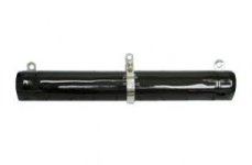
I have a pair of these resistors: D225K10RE - OHMITE D225K10RE - RESISTOR, WIREWOUND, 10 OHM, 225W, 10% | Newark element14 US
I cut the side out of a PCAT tower and cut two tabs about 1.5" x .4". I bent the tabs up 90 deg and then bent the ends in .5" to insert in the ends of the logs. So the resistors sit up in the air, off the coffee table I work on amps on.
Resistors with a smaller hole, I stick a screw up through a plate of sheet metal. Then I put a wooden or plastic torus at the bottom to hold the resistor up off the plate, so I don't burn the wood. A nut on top holds the resistor on.
I cut these sheet metal plates with a die grinder or air shear. Use safety glasses of course.
Yes, once you have a safe place to dump the current you can leave the amp on with the light bulb burning.
If I put a salvage speaker in series with a faulty amp, I put minus to minus 4700 uf 200 v capacitors in series with it. Any cap over 1000 uf would be okay. I use the caps that are too old that I am suspicious would blow up as rail caps in a repaired amp. The DC voltage out the speaker terminal hasn't blown one yet.
You may find old appliance heating elements make suitable load resistors for amps, by measuring their resistance. Unfortunately you can't take a DVM into Goodwill to measure them. I've got an old room heater with a bad tip-over switch that the heating element is useful.
As long as the op amp is getting its +-10 v don't worry about the rail voltages collapsing from A to B. That is what the series light bulb or room heater is for.
Attachments
- Status
- This old topic is closed. If you want to reopen this topic, contact a moderator using the "Report Post" button.
- Home
- Amplifiers
- Solid State
- Crown DC300A Repair/Restore