Thanks for the info guys my am is running at 14 m amp never gets warm cold a fridge lo.l as for class b I thought it was the worst amp to have as you hear folk go on about class A amps the amps I have are very good better than my tripath for musicality with deep bass I would like it bit more from the amp its a old amp I might replace all the caps just freshen it up I noticed a 2.2 electrolytic capacitor on the singnal in I am sjre a nice polypropylene would clean things up dkes anyone know any thing else I can do thank you to everyone who has took the time to reply deeply appreciated
On the older power amp PCBs with TO3 power devices, we did glue the bias transistor to the driver heatsink. We found out at some point that the proximity of the bias transistor to the driver heatsink worked well enough to give thermal feedback without gluing.
On the type VIII PCBs we did fit a coupling bar/heatsink on most PCBs. This cools the pre-drivers and keeps their chip temperatures similar to the bias transistor. Even so the bias still runs up with temperature partly due to the lower current sense resistors in the output stage. We control this with increased thermal feedback from the power transistor mountings.
It is pointless to run a amplifier designed for class B in class AB. The crossover distortion spikes minimise at just a few mA in each power transistor. Increasing the bias current inverts the crossover spikes due to the doubled Gm in the output stage and distortion then increases but not drastically. I would definitely not set the bias above 30mA as measured in one rail at no load.
On the older power amp PCBs with TO3 power devices, we did glue the birectifierstor to the driver heatsink. We found out at some point that the proximity of the bias transistor to the driver heatsink worked well enough to give thermal feedback without gluing.
On the type VIII PCBs we did fit a coupling bar/heatsink on most PCBs. This cools the pre-drivers and keeps their chip temperatures similar to the bias transistor. Even so the bias still runs up with temperature partly due to the lower current sense resistors in the output stage. We control this with increased thermal feedback from the power transistor mountings.
It is pointless to run a amplifier designed for class B in class AB. The crossover distortion spikes minimise at just a few mA in each power transistor. Increasing the bias current inverts the crossover spikes due to the doubled Gm in the output stage and distortion then increases but not drastically. I would definitely not set the bias above 30mA as measured in one rail at no load.
Thank you my bias is set to around 14 mv each channel is this ok? and would using two bridge rectifiers and separate capacitors for each channel improve sound quality? thank you
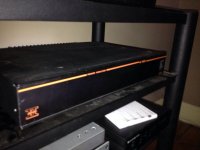
Bep powel you need to start selling these in kit form A.S.AP and sell them on ebay.awsome how old this amp the year 18 0 5 lol.Honest I have just put on my very detailed tripath amp on this crimson is in a diffrent league like a good valve amp honest I cant stand some naim.amps they dont sound this good I love realisim I modify dacs and cd players I have built a amp in the past in kit my knowledge on cds and dacs is good but not so much on amps this amp loves my bt mains conditioner it sound more real what wasnthe top model of crimson ? Surely cant be a whole.lot better than this well.done to the desinger I love this amp well it just lets the sound through the way I I like it
Thanks for your very kind comments on the Crimson amps. We did supply kits with "dual power supplies". We duplicated the rectifier and capacitor assembly and commoned the two centre taps. I do not have a diagram for this at the moment but I shall make one and publish a link to it in the next couple of days. A bias of 14 mA may be a bit low. Adjust the pot for say 17 mA at switch on and check after a few minutes that it has run up to 19 mA. If the bias overshoots beyond 20 mA power down and redo the process from cold. If you are intending on working on the amp "live" you should first ensure all that all exposed mains connections are shrouded or sleeved including the mains fuse. Always use a residual current circuit breaker in the mains supply.
There were and are now much more high end Crimson designs see:- Crimson Products Limited
There were and are now much more high end Crimson designs see:- Crimson Products Limited
Bepo,
the original CK1100 kit booklet and the diagrams that came soon after all showed a two channel set up with twinned rectifiers. The commoning of the Centre tap to the two channels causes hum and buzz.
The Crimson ground wiring set up does not work.
It took me more than 20years to discover why.
A multichannel amplifier using a centre tapped transformer must use ONE rectifier to supply all channels in parallel.
Or use 4 isolated secondaries feeding dual rectifiers to feed the isolated two channels.
Bepo,
the original CK1100 kit booklet and the diagrams that came soon after all showed a two channel set up with twinned rectifiers. The commoning of the Centre tap to the two channels causes hum and buzz.
The Crimson ground wiring set up does not work.
It took me more than 20years to discover why.
A multichannel amplifier using a centre tapped transformer must use ONE rectifier to supply all channels in parallel.
Or use 4 isolated secondaries feeding dual rectifiers to feed the isolated two channels.
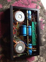
My CK1100 has zero buzz and hum. There's one transformer and 2 metal bridge rectifiers and 4 caps (8 with my mods) with what may be separate windings from memory, they're definitely at different sections of the circumference.
I have original 15015s on some CE1004, so I think you have one CE0608 and one CE1004. Both are 60W into 8R, but the CE0608 is SOA restricted into 4R as most modern speakers are.the 3055 35 - 01b version must be one of the smaller ones, maybe the 608
version iv is very early.
Brian can probably tell you how old.
the 15015 may be replacement devices for damaged outputs.
As far as I remember the Quantum had dual secondaries, but it was a long time ago to recall accurately.
And Yes, I called the factory and asked about adding another 2pr of 4700uF caps to the original complement of 2pr of 4700uF caps.
It made quite a difference to bass response.
The next I built from just new boards and I jumped straight to 3pr of 6800uF per channel. Four times the standard PSU smoothing.
That again improved bass.
In all these two channel builds I followed the Crimson instruction (I now had three sets) to wire up the grounding.
All had hum and buzz.
I agree with Andrew it is difficult to get the earthing right on complicated systems. I have done a diagram for dual power supplies showing the use of star earthing. This should be fine with a single transformer. However, dual mono would be even better with either 2 transformers or 4 secondary windings on a single transformer, the latter seem rather rare.
See diagram:- http://homepage.ntlworld.com/bepowell/schematics/StDual.pdf
The diagram is unchecked any comments would be appreciated.
See diagram:- http://homepage.ntlworld.com/bepowell/schematics/StDual.pdf
The diagram is unchecked any comments would be appreciated.
Hi Kevin. I desigend the Crimson stuff, I married a Tams girl and am in Newcastle under Lyme! On my webspace are many of the schematics:-
Index of /bepowell/schematics
There are a lot of tweaks for the PCBs as well as newer types. Do contact me if I can help.
Index of /bepowell/schematics
There are a lot of tweaks for the PCBs as well as newer types. Do contact me if I can help.
I've got a pair of these monoblocs I built about 15 years ago that I just powered up. Sound is still surprisingly good so I want a tweaksee if I can improve it. Anyone got a schematic or a circuit diagram, mine have long gone
Kev
- Status
- This old topic is closed. If you want to reopen this topic, contact a moderator using the "Report Post" button.
- Home
- Amplifiers
- Solid State
- Crimson Elektrik power amps