the 3055 35 - 01b version must be one of the smaller ones, maybe the 608
version iv is very early.
Brian can probably tell you how old.
the 15015 may be replacement devices for damaged outputs.
What are the drivers?
The quasi needs very fast drivers and if they were damaged, slow ones may have been substituted.
The transformer looks very similar to standard Crimson style.
There is nothing special about a Crimson Pre-Amp, other than it's unique casing.
All you need is a decent pre-amp that gives you enough gain to drive the power amps.
Crimson were very good back in their era but their designs have been surpassed many times over with modern counterparts.
If you can ascertain the input requirements of the power amps you can easily build a pre-amp to suit them.
I can't believe that Crimson, like Quad were still using the 2N3055.
There was a post on here earlier with a request for help with a Crimson pre-amp. Crimson had scrubbed the numbers off the op amps used in it, but I'd bet they were no other than members of the NE5532 family.
Last edited:
The issue 4 power amp PCBs date from about 1979 and were in five different versions. They gave from 40 to 100 Watts typically. If you post a pic I can tell you a bit more. We did make better sounding PCBs later. The best of the metal can type PCBs (TO3) was issue VII which was in production until superceded in 1999.
All my early Crimson PCB modules were the 2n3773 series vii.......I can't believe that Crimson, like Quad were still using the 2N3055........
They are good.
I still listen to one stereo amp I recently rebuilt.
You should be careful not to increase the bias current too much, as it will cause more heat to be created in the output and driver transistors, which could result in thermal runaway of the output stage = overload = dead amplifier in very short time. If you increase the air flow or heatsink size ( see this Usher R1.5 power amp to see the size of heatsinks needed for a class A biased amplifier ).
The Crimson amps are Class B and designed that way. They are what they are.
You won't get much bias current without mods anyway, a quick Spice sim showed about 0.5A - barely partial class A. Even at that level the heatsinksing looks inadequate.
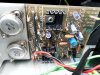
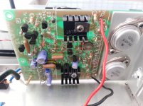
On one of your modules the bias transistor is not in contact with the driver heatsink. It looks like its been replaced with something with different pinout as it should have the flat side facing the heatsink and glued to it.
Your modules look like they are CE608 or CE1004 (nominally 60W into 8 Ohms or 100 into 4) as the amp has one of the smaller Crimson transformers and power is taken from the inner taps (26VAC). You should find the DC power to the amp modules is + and - 36V.
If you can read the values of R14,15,19 and 20 that should tell us whether you have CE608 or CE1004. Also confirm the DC supply voltage and the diameter of the transformer.
You won't get much bias current without mods anyway, a quick Spice sim showed about 0.5A - barely partial class A. Even at that level the heatsinksing looks inadequate.
On one of your modules the bias transistor is not in contact with the driver heatsink. It looks like its been replaced with something with different pinout as it should have the flat side facing the heatsink and glued to it.
Your modules look like they are CE608 or CE1004 (nominally 60W into 8 Ohms or 100 into 4) as the amp has one of the smaller Crimson transformers and power is taken from the inner taps (26VAC). You should find the DC power to the amp modules is + and - 36V.
If you can read the values of R14,15,19 and 20 that should tell us whether you have CE608 or CE1004. Also confirm the DC supply voltage and the diameter of the transformer.
Thank you for that you are very knowledgeable is that a bad thing class b I wentbto my mates and he made the outout m volts to about 14. 1 and the otherside 14.3 it was 13 he did not know how much current u could safly put through do you ? Is it possible.to makenthis amp.class.ab ? Thanks again
I've had my CE1704 modules at 0.25A quiescent for about 10 years no problem. The original current was 20mA. Gets warm after a few hours, current is stable. Sound quality may be the minutest bit cleaner at low but not quiet volumes, hard to tell the difference really, I've heard much bigger differences changing one cap in the amp.
err.. not really!Thank you for that you are very knowledgeable
Nope. The vast majority of amps on the planet are class Bis that a bad thing class b
I can't be sure what that means. Could be :I wentbto my mates and he made the outout m volts to about 14. 1 and the otherside 14.3 it was 13
A) output offset voltage in mV
easy to measure with a millivoltmeter across the output terminals
B) idle bias current in mA
more difficult to measure as you have to unsolder a power connection
to insert a milliameter in series.
There is only one adjustment on the Crimson amp boards and that is for adjusting the idle bias current B). Turning it may also cause measurement A) to change a little bit.
Nohe did not know how much current u could safly put through do you ?
Technically increasing the bias any amount makes it class A/B but as I said before you can't increase the bias very much with the trimpot on the standard board. I beleive Crimson set the bias for minimum distortion anyway. The optimum bias was pretty low at about 20mA into the positive supply terminal. This implies that increasing the bias just makes the distortion worse. Doug Self goes over this at length in his Audio Power Amplifier Design Handbook.Is it possible.to makenthis amp.class.ab ? Thanks again
If you do increase the bias then check that the output transitors don't get too hot. Note: don't touch them with power applied as they can be at full DC supply voltage. Probably better to check the heatsinks don't get anything more than hand hot. Crimson amps often had 70 degree C over temp cutouts fitted to the L bracket. You have heatsinks with a few short fins bolted to the amp modules with the chassis back panel sandwiched between them. This means the output transistors could get too hot before the heatsinks feel hot.
Last edited:
The CE amps have output triples...........On one of your modules the bias transistor is not in contact with the driver heatsink. It looks like its been replaced with something with different pinout as it should have the flat side facing the heatsink and glued to it............
The temp compensation is monitored on the pre-drivers, not the drivers.
On my PCBs the three To92 transistors are glued to a metal strip.
Edit.
No, that applies to the series viii pcbs, not the earlier series vii.
On the vii one driver sink has a to92 glued to the side.
The post22 pic of the 15015 shows this.
Last edited:
Andrew,
Yes, another little factoid for the Crimson info files. I have a pic of an Iss.5 board that also has Tr5 glued to Tr11 heatsink. Don't know about Iss.6
Do you think this was design oversight on the early versions? or was the Series 8 with Tr5,9,11 bonded to metal strip just a refinement?
Yes, another little factoid for the Crimson info files. I have a pic of an Iss.5 board that also has Tr5 glued to Tr11 heatsink. Don't know about Iss.6
Do you think this was design oversight on the early versions? or was the Series 8 with Tr5,9,11 bonded to metal strip just a refinement?
Last edited:
- Status
- This old topic is closed. If you want to reopen this topic, contact a moderator using the "Report Post" button.
- Home
- Amplifiers
- Solid State
- Crimson Elektrik power amps