planet10 said:This one is fairly respectable... a couple Joes have compared it favorably with much higher priced transformers.
http://www.edcorusa.com/transformers/audio/wsm/wsm10k-10k.htm
And it's not even $10. No more "big money" excuses now.
")
se
Steve Eddy said:
No more "big money" excuses now.
Indeed, it would be hard not to try it now.
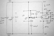
OK - here it is then...
Some of the values are approximate.
The design features are
VN66afd / 88afd sounded better than some other types
very low noise power supply ( I noticed recently that alkaline sounds better that lead acid hence the dropper resistors to a BG I guess )
The voltages drops across the o/p stage are optimised to give constant power so hopefully least memory distortion.
I guess the trimmer pot ( to set the bias ) could have another dropper resistor to the battery pos terminal and another decoupling cap.
each channel should have seperate PSU
more current and / or voltage is OK up to about 0.3W across mosfet
of course it does not have to be batteries but TR & diodes would need extra filtering to get the noise down
Which reminds me, did you ever come to a conclusion about snubber caps/resistor etc across the TR secondaries ? I still regard this as a miracle mod for anything that does not have it already.
cheers
mike
Attachments
Of course, a valve phase splitter might sound nicer
Probably, but having tried lots of them, to my ears nothing beats a transformer. The bad rap PP amps have is largely due to the phase splitters.
analog_sa said:
Probably, but having tried lots of them, to my ears nothing beats a transformer. The bad rap PP amps have is largely due to the phase splitters.
Mm... interesting, I will be interested to see how good my mosfet phase splitter pre can get, but I am not expecting it to match my TVC pre.
I was quite suprised that peter says that his TVC softens the treble sometimes.
Peter - what preamp are you using that has clearer treble and better dynamics ? Most of the people that I know that use TVC regard it as the most transparent option available.
mike
I'm using heavily modified ML380S.
On classical and jazz TVC is better: cleaner and more natural.
On electronic music (house, industrial), active preamp seems like a better choice.
The early versions of TVC, were definitely reducing highs; for instance in my friend's system with Alephs 2, he didn't like transformers at all, but they worked great with GC. The current version is better in that regard, and it's hard to say if such reducing occurs.
They are definitely less colored than a ML preamp, yet they still have a sound of their own.
was quite suprised that peter says that his TVC softens the treble sometimes
I've been complaining about this here and in other forums since the day i bought mine. It seems like i was just unlucky to get the spec oriented MK2 'improvement' upon the original. It seems both Mk1 and Mk3 are excellent but based on this experience i'll never again buy anything from S&B before a firsthand listen.
Have you tried using half of the primary instead of all of it ?
I prefer this option.
It means that my 'balanced in' is now psuedo balanced with the earth from the source connected to the centre of a resistive divider across the balanced o/p (and to the case of the TVC)
Using the 102 with a primary centre tap earth is not a good idea as the windings are not symetrical and in these circumstances I do find that treble is reduced.
But I prefer this half primary option even for unbalanced in.
mike
I prefer this option.
So do i. Btw i've only used it unbalanced.
Since you mentioned it Peter...
Which of these two looks better?
From AD815 datasheet :
Peter Daniel said:How would it be to combine transformer with an active line driver, like AD815 for instance (or discreet buffer)? I think there is even an example like that in application notes.
Which of these two looks better?
From AD815 datasheet :
Another means for creating a differential signal from a single ended signal is to use a transformer with a center-tapped secondary. The center tap of the transformer is grounded and the two secondary windings are connected to obtain opposite polarity signals to the two inputs of the AD815 amplifiers. The bias currents for the AD815 inputs are provided by the center tap ground connection through the transformer windings.
One advantage of using a transformer is its ability to provide isolation between circuit sections and to provide good commonmode rejection. The disadvantages are that transformers have no dc response and can sometimes be large, heavy, and expensive.
This circuit is shown in Figure 51.
An externally hosted image should be here but it was not working when we last tested it.
Two types of circuits can create a differential output signal from a single-ended input without the use of any other components than resistors. The first of these is illustrated in Figure 52.
If a resistor (RF) is connected from the output of Amp 2 to the + input of Amp 1, negative feedback is provided which closes the loop. An input resistor (RI) will make the circuit look like a conventional inverting op amp configuration with differential outputs. The inverting input to this dual output op amp becomes Pin 4, the positive input of Amp 1.
The gain of this circuit from input to either output will be ± RF/RI. Or the single-ended-to-differential gain will be 2 X RF/RI.
The differential outputs can be applied to the primary of a transformer. If each output can swing ±10 V, the effective swing on the transformer primary is 40 V p-p. The optional capacitor can be added to prevent any dc current in the transformer due to dc offsets at the output of the AD815.
An externally hosted image should be here but it was not working when we last tested it.
wensan said:It is a hard job to translate this article.
Can we have an idea what are they trying to achieve?
If it's just a differential signal from a single ended signal, it's too complicated and certainly far from the GC spirit.
Carlos
carlmart said:If it's just a differential signal from a single ended signal, it's too complicated and certainly far from the GC spirit.
Hi Carlos,
What do you think of the two designs from the AD815 datasheet?
Do you think they have any potential for sounding good?
I need a simple, but very good, preamp to convert the single-ended signal from my DAC(Tube-Lover's TDA1541A kit) to differential for the Zeus amp I'm building.
I suppose it really wouldn't cost too much to just breadboard Figure 51 and see how it works. But, I don't know what type of input transformer to get - 1:1, etc
Another DIY'er in LA!
Hey Acliao,
Good to see someone else from this town is active around here. Are building anything interesting right now?
Any advantage over Figure 51?
I suppose that since Fig 53 has a transformer on the output, it is easier to lock the output impedence at a desired level like the standard differential 600 ohms or lower if need be.
Of course, you could just add another 1:1 line output trans to Fig 51 and get the same effect.
Hey Acliao,
Good to see someone else from this town is active around here. Are building anything interesting right now?
Rowland Synergy uses similar topology from Figure 53 mentioned above.
Any advantage over Figure 51?
I suppose that since Fig 53 has a transformer on the output, it is easier to lock the output impedence at a desired level like the standard differential 600 ohms or lower if need be.
Of course, you could just add another 1:1 line output trans to Fig 51 and get the same effect.
- Status
- This old topic is closed. If you want to reopen this topic, contact a moderator using the "Report Post" button.
- Home
- Amplifiers
- Chip Amps
- Creating a differential signal from a single-ended signal for bridged amps