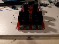
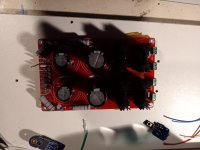
hiHi all,
I have the CRCRC almost done, but I can't decide what size filter capacitors to buy.
6x 10 000 uF
6x 15000 uF
6x 18000 uF
6x 22000 uF
I will power one board with 2pcs JAT501 (100W/ 4ohm). I will use 400W toroidal transformer, common for both channels
Thx.
The JAT501 from the web site is the standard Doug Self blameless amplifier with same topology used in many commercial amplifiers (see figure 33): http://www.douglas-self.com/ampins/dipa/dipa.htm . The blameless amplifier has the beta enhancer transistor though and some resistors value optimization….
This is not a class A amplifier but class B or class AB 100W / 4 ohms thus no need for real big PSU cap here. Even an C-R-C PSU may be overkill for your selected amplifier need…. At least use a very small R value such as no higher than 0.1 or 0.15 ohms to prevent PSU too high voltage modulation upon high power demands…
Fab
Last edited:
Hi all again,
I'm not addressing here whether I'm going to power the amplifier A or AB with that source. Rather, my concern is what optimal capacitance of filter capacitors to choose for my 2x100W amplifiers.
R between capacitors has the value 0,16 (2x). With my 25V AC transformer there will be approximately 35V DC at the output and at full build up of the amplifier there will be a drop of about 2V
In practice, I will use the amplifier up of 1 to 10 W
My point is that You need C-R-C type filter for class A amplifier. This specific thread board has been designed for that. More simple and smaller PSU boards are available for class AB amps where PSU requirements are less stringent since current demand is more function of output power compared to class A power where it is the reverse….thus no need for multiple capacitors with R in between…
If you want to use that PSU board than for such a low power amp current requirement you can use a smaller cap total value than the one you have listed. There is no formula because it is a matter of choice depending on how much ripple you allow and how the power amp PSRR is. In that case the PSRR is good. The cap value is one parameter but another one is the ESR of the caps where it should be low.
From experience my recommendation with your 400VA transformer should be about 10000uF low ESR by voltage polarity….
Fab
Hi Prasi,
I have the QModo jig, but do not have an O'scope yet. I looked at all the QModo test results for the Antek transformers and it seems that Rs is in the range of 15R - 20R with transformers 300-400VA and secondaries of 18V - 36V. I think that I will try this resistor range using C2=10nF and Cs=150nF.
Question: If I decide to use the default value range for Rs as shown on the schematic, I would still have to add the numerous 10nF film caps as shown on schematic ?
I was planning on using a AS-3230 300VA, 2x30V sec or a AS-3232, 2 x 32V sec to end up with about 40V DC useable.
Question: Will the CRC board drop about 2V ? Trying to size the correct transformer.
Thanks for the help,
MM
Thanks prasi,
I guess what I was trying to ask is: From the Anteks test results reported, using a resistor in the ranges reported would be better than using the default value of 150 ohms for the value of Rs. Most of the testers used a resistor value close to what they measured, rather than the actual measurement.
I think I would be fine using this approach, and leaving out some of the film cap's. Comments?
Hi MM,
Yes those will be fine, just calculate the resistor value based on your voltage.
R= (VCC-Vf)/ (desired LED current).
You might want to run them at say 3-5 mA so they dont get super bright.
see attached excel in sheet named example calculation.
Yes those will be fine, just calculate the resistor value based on your voltage.
R= (VCC-Vf)/ (desired LED current).
You might want to run them at say 3-5 mA so they dont get super bright.
see attached excel in sheet named example calculation.
Attachments
Hi All,
I read in the thread about due diligence when mounting the diodes to the heat sinks to prevent conduction. I am running low on mica pads, so I am going to use some sil pads and mount using a shoulder washer through each diode and a nylon bolt & nut to secure both diodes to the sink. Since using sil-pads, I was not planning on any thermal grease. My diodes are metal backed. Comments / different / better ideas are welcome.
Thanks,
MM
I've made many PS's and always used SIL's and nylon shouldered spacer/washer on the diodes, without any issues, ever!
Do use a flat washer on each side of the shouldered spacer, and a lock washer and plain nut - I attach a shot to explain more - Photos tell the story more than any words. I would use metal screw, nut and washers because nylon may not be able to squeeze the assembly enough when tightened.

Do use a flat washer on each side of the shouldered spacer, and a lock washer and plain nut - I attach a shot to explain more - Photos tell the story more than any words. I would use metal screw, nut and washers because nylon may not be able to squeeze the assembly enough when tightened.
Last edited:
Hi Folks, a quick question if I may,
I have soldered 4 x 2 post terminal blocks for AC1 and AC2, rather than spades. I am using 1 transformer with dual secondaries and 1 psu for one channel.
My question is: Can I insert a single secondary wire into one side of a 2 post terminal block and expect the psu to function properly, or do I have to desolder and change to spades. Thanks for the help.
MM
Prasi and other builders,
Please see attached pic with iec inlet, soft start, transformer, and the psu. Primaries wired in parallel for 115V. Secondaries wired as shown. AC1 has a blue/ green with confirmed continuity. AC2 has blue /green with confirmed continuity.
Should be good to continue with wiring, Correct ?
Thanks

Please see attached pic with iec inlet, soft start, transformer, and the psu. Primaries wired in parallel for 115V. Secondaries wired as shown. AC1 has a blue/ green with confirmed continuity. AC2 has blue /green with confirmed continuity.
Should be good to continue with wiring, Correct ?
Thanks
- Home
- Group Buys
- CRC Power Supply (Class A amplifier)


