I just want to clarify that the above circuit may work if one is careful with grounding strategy. Nothing should be accidentally or grounded without purpose.
I have used something like this on a Class AB and did not have hum. Lately using Class A amps with lower PSRR and ground loops seem to take their toll.
I have used something like this on a Class AB and did not have hum. Lately using Class A amps with lower PSRR and ground loops seem to take their toll.
Shorting inputs means connect +ve input to -ve input at the input terminal block.
Hum is there when the inputs are shorted as per your mean, but the hum gone after shorting both input grounds each other like this
Don’t know if this is recommended solution as haven’t seen this type to reduce the hum, it might help others so sharing the pic

After feeling rather frustrated with unresolvable hum I decided to start with a clean slate so I pulled everything out. I even switched to an earlier amp that I know is pretty quiet.
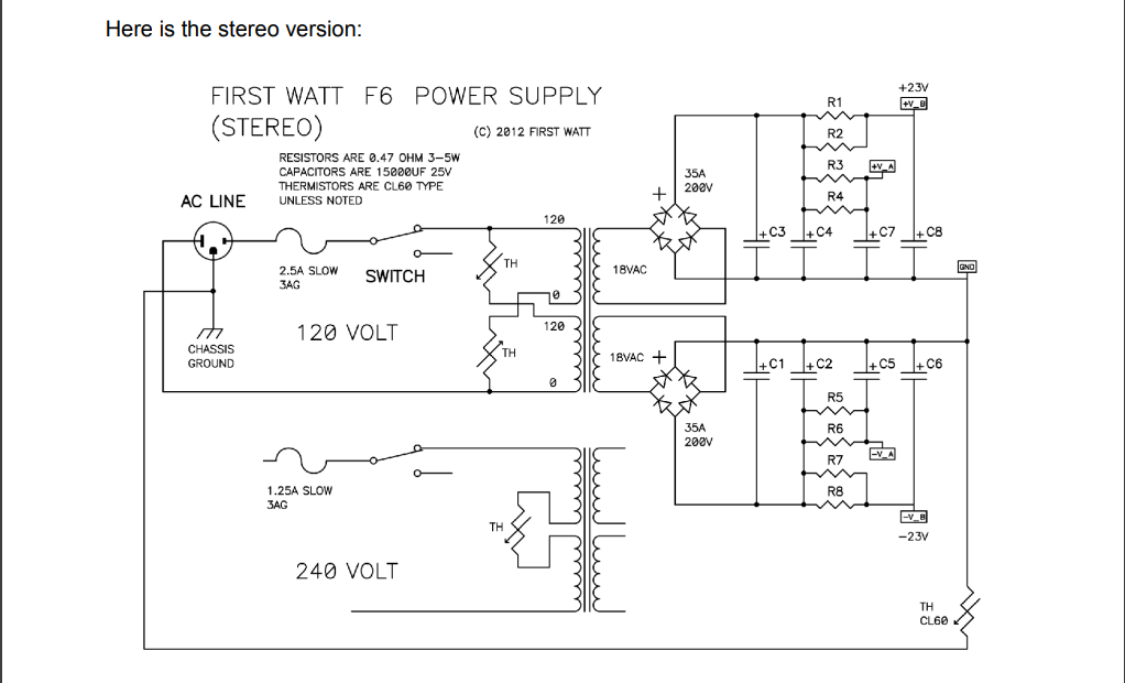
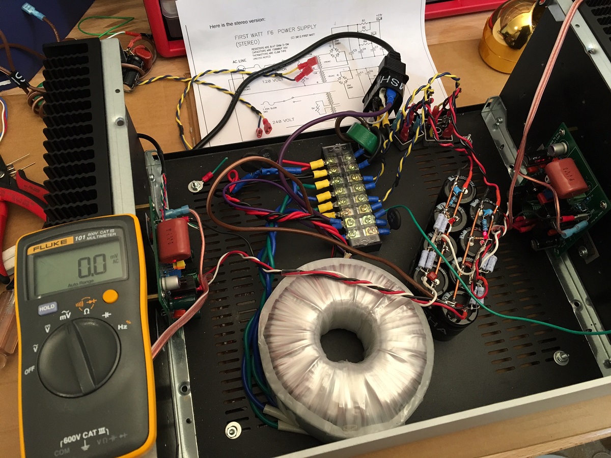
So I followed the Pass F6 PSU schematic to a "T" (except I added a 330pF+10R snubber and bypass film cap on the CRC). I used qnty 8 x 33mF 25v CDE caps, Panasonic 0.47R metal film 3W resistors, and external monolithic full wave bridges, 8D-20 NTC's (vs CL-60's). I made everything P2P using 12ga solid copper wire for the ground bus.
The amp I am using is the Apex FX8 Bimo mod (nominally a Class AB with Renesas 2SK1058/2SJ162 lateral FETs), designed for 35v rails. However, I am using a 400VA Antek 18v-0-18v toridal trafo for 24v rails and biasing it at 1.00 amp for Class A operation. The rails sagged to +/-22.7v under 1amp load but that is ok. Bias setting is rock stable with lateral FETs. DC offset has no adjustment but controlled by thermally bonded and matched input LTPs and is about 10mV and stable.
So get this, with the source (my iPhone 6s) connected to the input, I measure 0.0mV noise at the speaker output. Absolutely no noise or hum at all. Cannot hear a thing with my ear pressed to the speaker.
It sounds really nice and I am thinking this is not a bad Class A setup as it pretty low distortion by design and has the typical Apex 30dB gain so anything can drive it, including my phone.
So there you have it. If you want no hum - follow the above schematic exactly. This PSU has separate final RC on the CRC to give additional stereo separation as each amp sees its own 33mF cap separated by 0.47R.
I might put the Pass Class A amps back in at a later time to see what the noise at the speaker output is. I doubt it can beat 0.0mV of the Bimo FX8 though. I might keep this amp in here a bit longer and have some fun.
Attachments
Thanks XRK, is the hum issues only with the CRC psu boards that we brought in the group buy or is it going to be the same problem with other Psu boards (I have couple of universal psu boards paired with pair of monolithic bridge modules) if using as dual PSU powered by a single transformer? I planned to make it dual psu with universal PSU boards for my upcoming Sony VFET-2 kit which is almost completed.
See the very nice explanation given by Shaan and by AndrewT. It makes things pretty clear. CRC Power Supply (Class A amplifier)
It will be a problem with single transformer + 2 psu + a source whose grounds are joined. have you tried suggestion given by Shaan?
It will be a problem with single transformer + 2 psu + a source whose grounds are joined. have you tried suggestion given by Shaan?
No suggestion by Shaan is too complicated for my DIY skills to scratch the psu board surface and solder the +/- and centre tap directly to the board. I haven't attempted that but instead I have started using a single CRC psu board for my V4 amp and now there is no hum issue.
I think the short story is that using two PSU boards is wrought with potential ground loop issues leading to hum. Solvable, but I have tried for a lon time and not making much progress. So I think using the subject CRC PSU of this GB should only be used for single PSU applications if hum is to be avoided.
The F6 PSU I made with P2P using 8x 33mF caps is indeed very effective. I wonder if using NTC's directly in primary trafo windings contributes to lower noise as it provides natural 0.25R damping resistor? I have never had as quiet a linear trafo PSU before. I could use the Bimo FX8 as a headphone amp.
The F6 PSU I made with P2P using 8x 33mF caps is indeed very effective. I wonder if using NTC's directly in primary trafo windings contributes to lower noise as it provides natural 0.25R damping resistor? I have never had as quiet a linear trafo PSU before. I could use the Bimo FX8 as a headphone amp.
See the very nice explanation given by Shaan and by AndrewT. It makes things pretty clear. CRC Power Supply (Class A amplifier)
It will be a problem with single transformer + 2 psu + a source whose grounds are joined. have you tried suggestion given by Shaan?
Hum is not with single transformer with 2 psu, it’s observed even with 2 transformers and 2 psu
yes, it will hum.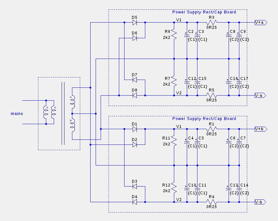
I have tried this, it hums.
There is a connection between the two channels and that connection form part of a loop. It will pick up interference as soon as the loop is completed by signal interconnects to a Source that has a commoned Signal Return.
No. Is this what you refer to in your edit?As I understand it on a dual rail supply the ground is just a reference. The current should go out on V+ and come back on V-.
the Power Zero Volts passes current in both directions whenever the +ve rail current is not instantaneously identical to the -ve rail current.Although if you have any local smoothing caps on the channel boards, then the ripple they take out will go out on V+ and come back in on ground (or go out on ground and come back in on V- for the negative side).
Either way, I suspect it doesn't do any harm to have all 3 twisted together, but I'd love to hear other opinions.
[Edit: oops, I wasn't on the last page of the thread. I see AndrewT already addressed this....]
The design is made for two separate windings (AC) and this circuit is designed and optimized for this.
- Why do you absolutely want to use two CRC circuits with one transformer?
- Why do you absolutely want to use a mid-point transformer?
Here's an optimal use of this PSU:
Amplificateur USSA: Dans le ventre de la bete - construction par Pinnocchio - Page 7
- Why do you absolutely want to use two CRC circuits with one transformer?
- Why do you absolutely want to use a mid-point transformer?
Here's an optimal use of this PSU:
Amplificateur USSA: Dans le ventre de la bete - construction par Pinnocchio - Page 7
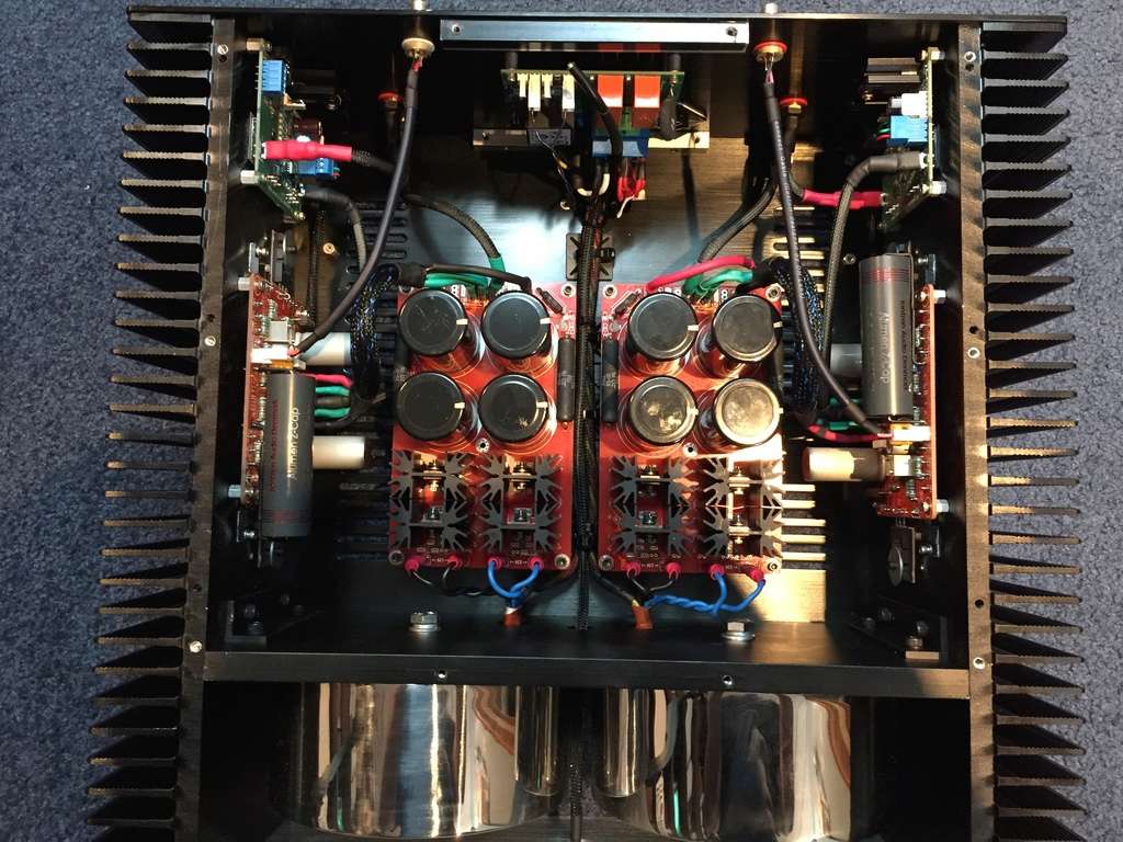
Here is the feedback of the person who realized this set.
"The power supply in an amp makes all the difference, a huge difference in fact. That's why you should never be afraid to invest in it. The double bridges of ultra-fast diodes with "soft-recovery", the Mundorf M-Lytics MLGO condos with low impedance and very high ripple and the PSU layout very well done, high quality transformers. This is all very important. This results in a lower impedance power supply and much lower noise at the end. The result: lots of low-level micro-detail microphones that were hard to hear or went unnoticed, improved dynamics, a super-silent (very black) background, and micro-details that are no longer masked or washed out (washed)."
"The power supply in an amp makes all the difference, a huge difference in fact. That's why you should never be afraid to invest in it. The double bridges of ultra-fast diodes with "soft-recovery", the Mundorf M-Lytics MLGO condos with low impedance and very high ripple and the PSU layout very well done, high quality transformers. This is all very important. This results in a lower impedance power supply and much lower noise at the end. The result: lots of low-level micro-detail microphones that were hard to hear or went unnoticed, improved dynamics, a super-silent (very black) background, and micro-details that are no longer masked or washed out (washed)."
I was using it with Antek trafos with separate windings. The issue seems to be trying to use it as two separate PSU's with two trafos (4 separate secondary windings as suggested) - I still get residual hum circa 1.1mV AC at amp outputs. I know this is a grounding issue, but even following carefully grounding schemes for separate monoblocks, the moment the common ground of the Left and Right source channels are connected results in hum. Perhaps it is an inevitable fact that this happens in dual PSU designs and to avoid one need to use one PSU for both amp channels.
I have bought these PSU's in fact to build a dual trafo, dual CRC PSU for the USSA5 as shown in your link - beautiful amp. Please show us explicitly a schematic diagram of the PSU connections and grounding. Scheme of this beautiful amp. Maybe we are still
Kissing something? Maybe we need to use balanced line drivers?
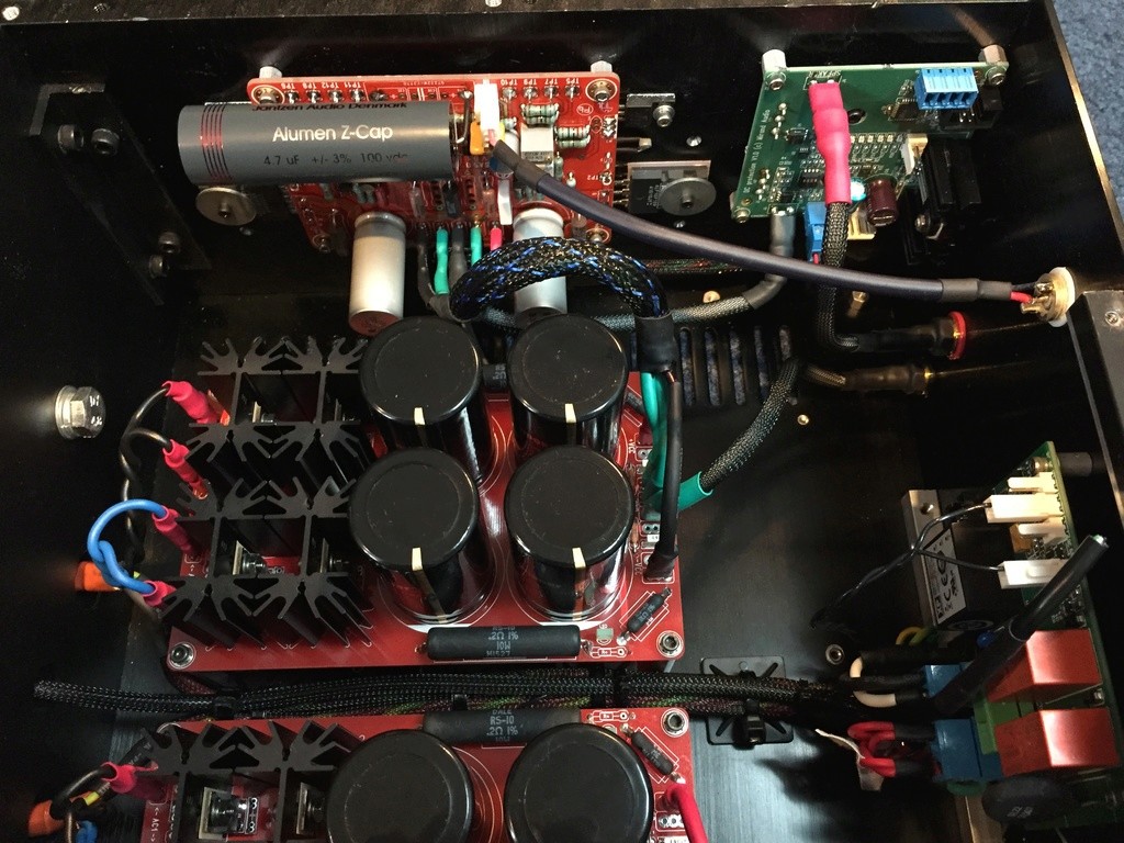
Just looking st he above image I can see that there is a total absence of any ground connection between the GND of both CRC PSU's to each other. It's like the amps are in separate boxes.
I have bought these PSU's in fact to build a dual trafo, dual CRC PSU for the USSA5 as shown in your link - beautiful amp. Please show us explicitly a schematic diagram of the PSU connections and grounding. Scheme of this beautiful amp. Maybe we are still
Kissing something? Maybe we need to use balanced line drivers?
Just looking st he above image I can see that there is a total absence of any ground connection between the GND of both CRC PSU's to each other. It's like the amps are in separate boxes.
Last edited:
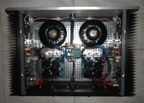
With the PSU models used in my USSA-5 (photos) which are in fact the same model as this wire and with more basic components I have absolutely no noise or blast or parasite.
For information, my inputs and outputs are always isolated from the box and only the grounding is connected to the box, each channel is completely separated from each other, all my amplifiers are connected so and I never had any surprises.
For information, my inputs and outputs are always isolated from the box and only the grounding is connected to the box, each channel is completely separated from each other, all my amplifiers are connected so and I never had any surprises.
Attachments
With the PSU models used in my USSA-5 (photos) which are in fact the same model as this wire and with more basic components I have absolutely no noise or blast or parasite.
For information, my inputs and outputs are always isolated from the box and only the grounding is connected to the box, each channel is completely separated from each other, all my amplifiers are connected so and I never had any surprises.
Is the ground on each PSU channel connected to earth(mains) GND via an NTC or ground loop breaker resistor and diode pair? It doesn't look like it from photo. This is electrical code requiremt for safety in USA (and I'm sure in Canada). For DIY it can be skipped to prevent hum - but the risk of shock should the transformer primary ever come in contact with the secondary is there. However small that chance is, electrical code requires it.
I'm not worried about connecting the PSUs to chassis gnd. With +/-25Vdc, the max voltage is 50Vdc which will not hurt you. If you do want to connect them to chassis, you can use a square bridge, cap and resistor for each one to chassis, but I have not done so for my Amps. I also set it up as a dual mono in my many amps. I would not connect two PSU to a single transformer with dual secondaries as my experiences with this arrangement have never been good. Preferably, use true dual mono setup and do not link PSUs together.
Do
Do
Hi Pinocchio,
Thanks for the input. Nice amp you have there - one of the best looking Class A amps I have seen. Too bad my trip to Montreal got cancelled or I would have probably seen this in person.")
The trick it seems is to not connect the PSU's together in any way. The 50v is not the worry. It's if there is an insulation failure on primary and it touches secondary - the amp circuits are energized with line 120vac or 220vac in Europe. That's when the GLB or NTC can save your life if you accidentally touch the amp in the wrong place. Albeit, it's a rare and difficult thing to happen.
Thanks for the input. Nice amp you have there - one of the best looking Class A amps I have seen. Too bad my trip to Montreal got cancelled or I would have probably seen this in person.
The trick it seems is to not connect the PSU's together in any way. The 50v is not the worry. It's if there is an insulation failure on primary and it touches secondary - the amp circuits are energized with line 120vac or 220vac in Europe. That's when the GLB or NTC can save your life if you accidentally touch the amp in the wrong place. Albeit, it's a rare and difficult thing to happen.
- Home
- Group Buys
- CRC Power Supply (Class A amplifier)