I used unshielded twisted pair (UTP) a lot, even though there are some here who keep reminding me that these ONLY work when the connections are balanced impedance.I have tried with shielded cables before, didn't make a difference.
I find that these unshielded twisted pairs perform as well as any coaxial that I have tried to compare them with my limited test equipment.
Dear all
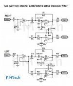
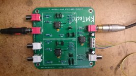
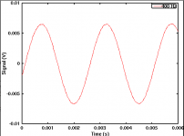
While I was off to get my hip dent lifted (or something like that) I got a delivery of a KMTech filter board. This filter board works with a bunch of OPA2134 FET input opamps (schematic and photo attached, note that the 20k resistors shown in the schematic are 6k2 on my board). I hooked up the KMTech filter instead of the existing ABACUS filter and got the attached signal at the output. Looks good to me! And I am happy to know it is possible to make the whole setup work with the TVC the way I intended at the beginning.
Just to see if the FET input makes all the difference, I installed NE5532s instead of the OPA2134s on the KMTech board. This gave a tiny hint of small pips in the output sine signal, but nowhere as bad as with the ABACUS board. So while the OPA2134 do make a difference, there are other things that are not right with the ABACUS. Apart from the OPA2134, the more obvious differences of the KMTech are smaller capacitor values and larger resistor values in the filter network; and the board itself is different, of course.
I'd really like to make the ABACUS filter work well, because the low pass filter includes a Linkwitz transform, and it has an additional output stage with variable gain. Both are needed for the speaker system. As I am still a bit clumsy with my new crutches (I can't use my hands to carry stuff to/from the workshop!), I need to think twice as hard about my next steps. Here are some ideas:
Any other ideas or suggestions? I'd really like to understand what's wrong with the ABACUS filter. If anyone has additional ideas, thoughts or explanations, I'd be happy to know!
While I was off to get my hip dent lifted (or something like that) I got a delivery of a KMTech filter board. This filter board works with a bunch of OPA2134 FET input opamps (schematic and photo attached, note that the 20k resistors shown in the schematic are 6k2 on my board). I hooked up the KMTech filter instead of the existing ABACUS filter and got the attached signal at the output. Looks good to me! And I am happy to know it is possible to make the whole setup work with the TVC the way I intended at the beginning.
Just to see if the FET input makes all the difference, I installed NE5532s instead of the OPA2134s on the KMTech board. This gave a tiny hint of small pips in the output sine signal, but nowhere as bad as with the ABACUS board. So while the OPA2134 do make a difference, there are other things that are not right with the ABACUS. Apart from the OPA2134, the more obvious differences of the KMTech are smaller capacitor values and larger resistor values in the filter network; and the board itself is different, of course.
I'd really like to make the ABACUS filter work well, because the low pass filter includes a Linkwitz transform, and it has an additional output stage with variable gain. Both are needed for the speaker system. As I am still a bit clumsy with my new crutches (I can't use my hands to carry stuff to/from the workshop!), I need to think twice as hard about my next steps. Here are some ideas:
- Try the OPA2134 FET opamps in the ABACUS.
- Use the KMTech capacitor and resistor values in the ABACUS board.
- Try the capacitor mod on the DAC output (as suggested by Hans), or insert an RC low pass filter in between the DAC output and the TVC input (even though the KMTech filter works well without this).
Any other ideas or suggestions? I'd really like to understand what's wrong with the ABACUS filter. If anyone has additional ideas, thoughts or explanations, I'd be happy to know!
Attachments
Dear all
Any other ideas or suggestions? I'd really like to understand what's wrong with the ABACUS filter. If anyone has additional ideas, thoughts or explanations, I'd be happy to know!
Do you mean you will be happy to get rid of them as mines?
I used unshielded twisted pair (UTP) a lot, even though there are some here who keep reminding me that these ONLY work when the connections are balanced impedance.
I used UTP also, for many different purposes. The cables work. The shielding effect doesn't work. (Since there is no shielding.)
I find that these unshielded twisted pairs perform as well as any coaxial that I have tried to compare them with my limited test equipment.
Especially since you have no idea what parameter should be tested and how. Required test equipment: an input of an amplifier, your hand, a speaker and your ear.
Scope usage has been refused.
[rant on]
Stop refusing my explanation why my scope won't give anything more useful than what I already provided in this thread. And stop trolling, please.
[rant off]
[rant on]
Stop refusing my explanation why my scope won't give anything more useful than what I already provided in this thread. And stop trolling, please.
[rant off]
Matthias,
This time I would like to ask you a question:
How do you connect a line of text to a previous posting as you did with "my explanation ......... provided", that's very convenient indeed.
Hans
How do you connect a line of text to a previous posting as you did with "my explanation ......... provided", that's very convenient indeed.
It works the same as inserting any other link / URL. You can find the URL to the specific post by right-clicking on the post number shown on the top right of the post. Insert this URL to your text using the globe/link icon in the post editor.
Try the OPA2134 FET opamps in the ABACUS.
That reduced the pips quite a bit, but did not remove them.
Try the capacitor mod on the DAC output (as suggested by Hans), or insert an RC low pass filter in between the DAC output and the TVC input (even though the KMTech filter works well without this).
Tried a 10 nF capacitor across the DAC output. No change at all.
So I guess I am up to order resistors and capacitors with the same values as those in the KMTech filter and see if this changes anything.
Any other suggestions or ideas?
That reduced the pips quite a bit, but did not remove them.
Tried a 10 nF capacitor across the DAC output. No change at all.
So I guess I am up to order resistors and capacitors with the same values as those in the KMTech filter and see if this changes anything.
Any other suggestions or ideas?
My feeling is that you concentrate too much at the end of the chain, resulting in symptom fighting instead of removing the cause.
All opamps tried by you, are more than able to deliver a perfect result, so let them alone for a while.
You should start at the beginning of the signal chain and go from there step by step.
1) You mentioned that with a 50 Ohm signal generator the signal from the filter is O.K., which shows that the filters are able to do their job.
2) An output cap on your DAC doesn't help either, so this part can be taken from the list also for the time being.
3) Next step in the signal chain is the TVC, so take it out and make a direct connection between DAC and ABACUS filter
Use the positive DAC output first and if everything is OK then connect as a next step to the negative DAC output.
If amplitude is too large, use a simple resistor divider.
Awaiting to hear the results.
Succes,
Hans
...Next step in the signal chain is the TVC, so take it out and make a direct connection between DAC and ABACUS filter
Use the positive DAC output first and if everything is OK then connect as a next step to the negative DAC output.
If amplitude is too large, use a simple resistor divider.
I did that. I used a 10k potentiometer to get to the same signal voltage as with my TVC tests, just so the data are comparable. The pips were gone.
More and more I'm getting the feeling that your DAC is not able to directly drive your TVC.
I don't think so (see post 25). Also, the signal at the TVC output is clean. If the opamp filter would work the way it was supposed to work, I'd expect it to output a clean signal too.
So the observation is that the signal at the filter output is distorted with the TVC at the filter input, but is not distorted with the potentiometer in place of the TVC. This tells me that the filter interacts with the TVC in some way, and this upsets the opamp somehow. The key will be to remove the interaction between the TVC and the filter.
So when you have finished the above test with positive results, the next step will be to place a buffer between DAC and TVC.
I could do that, but I already know that the whole thing does work without a buffer (using the eBay/KMTech filter instead of the ABACUS board). And I am too stubborn to dilute my crazy idea with a buffer that is proven to be unnecessary ;-)
Or no TVC")
Not yet -- maybe in a different project
I did that. I used a 10k potentiometer to get to the same signal voltage as with my TVC tests, just so the data are comparable. The pips were gone.
I don't think so (see post 25). Also, the signal at the TVC output is clean. If the opamp filter would work the way it was supposed to work, I'd expect it to output a clean signal too.
So the observation is that the signal at the filter output is distorted with the TVC at the filter input, but is not distorted with the potentiometer in place of the TVC. This tells me that the filter interacts with the TVC in some way, and this upsets the opamp somehow. The key will be to remove the interaction between the TVC and the filter.
Hi Matthias,
Glad to hear that you made one step forward in isolating the problem.
However I do not share your opinion that the filter is interacting with the TVC.
The fact that the TVC output is clean, only indicates that your scope cannot record the fast glitches.
Remember that you placed a buffer between TVC and filter and that the problem was still there ?
So I would advise you to place buffers between the DAC and the TVC, most likely there is the source of your problem.
A Dac is meant to produce a current output, preferably to the minus input of an opamp, thereby keeping the current source at a contant voltage.
In your case this current is led to a resistor to convert it to a voltage.
To also connect a complex load of a TVC is obviously one step too far.
Hans
Before placing the buffers between Dac and TVC, you could start by placing two 150 Ohm resistors instead, which is a bit easier.
This is of course only a quick step to get a first indication whether it is indeed the connection between DAC ands TVC that is causing the problems.
When the results are positive, then go for the buffers.
Hans
This is of course only a quick step to get a first indication whether it is indeed the connection between DAC ands TVC that is causing the problems.
When the results are positive, then go for the buffers.
Hans
Before placing the buffers between Dac and TVC, you could start by placing two 150 Ohm resistors instead, which is a bit easier.
Tried it. Result did not change.
Have you tried my ideas yet?
Aaargh, this got lost in my to do list. Just installed a T pad with 2 x 100 Ohms series and 3kOhm to GND (had these laying around on the workbench). The result is attached. Looking good! Still a bit shaky at the min/max, but maybe that's just noise.
Now what does all this mean? I am still tempted to think that the problem is not on the DAC side of the TVC, but rather on the filter side. What do you guys think?
Attachments
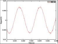
The T-pad you used will not attenuate the signal very much, but it will isolate the filter from any extremes of impedance presented by the transformer. We still don't know whether the main problem is some sort of HF energy from the DAC, or instability in the filter prompted by a termination impedance it doesn't like. This latest result points towards the latter, but on its own is not conclusive.
- Status
- This old topic is closed. If you want to reopen this topic, contact a moderator using the "Report Post" button.
- Home
- Source & Line
- Analog Line Level
- Crazy distortion problem with transformer and active filter (opamp / Sallen Key)