Jaap said:thanks again (all of you) for the interesting suggestions, i will certainly look into it.
I chose the ecl82/6bm8 because I have some (4 unused Telefunken and some Philips) and two rather good OPT's which were made for them. Are you gentlemen suggesting the ecl86 for better sound or for more power ? I suppose that I can use the same OPT with ecl86.
The sound depends much more on the circuit and how you use the tubes. You can get excellent results with both PCL82 and PCL86.
The OPT's can be good for both depending on the primary impedance etc....there are some overlapping specs which will work
for both.
Make no mistake: in the real world the ECC40 is better than its successor E80CC.Jaap said:I do not like Fet inputs because matching is a problem. The regulated screen supply is certainly on my list. And I have also some ecc40's (= e80cc) on the waiting line to put in a cathodyne splitter in some amp some day.
I have both of them and the former is a substantial more linear tube.
I have many ECC40's by Siemens, AEG Telefunken and Radio-Techinque France and they all perfom nicely. E80CC are Philips.
Jaap said:I saw somewhere EL803 tubes, is a better version of el83. Also a nice candidate in this class of tubes I suppose (?)
It can work good: specs close to the PCL86.
Cheers,
45
Jaap said:For some reason I like fiddling with tubes as ecl82/86 and el84 more than trying to get good sound out of 300B's.
300B's are very demanding tubes in terms of driving (the 45's also, regardless of output power).
You can make a "simple" amp but, very probably, it will have a vintage sound.
If you want make things a bit simpler better to go for 2A3's.
Russian 6C4C's (which are octal base 6A3's) are excellent. These have double-plates identical to RCA's but better filament suspension. The build quality and materials (for 1980's or older manufacturing) are truly outstanding.
IMO, they must be feed with DC filament supply for best results.
Cheers,
45
That is what I found out some years ago after building the "Flesh and Blood" (1/2 6sn7 => 1/2 6sn7 => 300B). There was a lot of fuss about it at that time but I believe it is a waste of too much money.45 said:
300B's are very demanding tubes in terms of driving (the 45's also, regardless of output power).
You can make a "simple" amp but, very probably, it will have a vintage sound.
Isn't 6S4 or 6C4 the russian variant of 6B4G ? If there is still room in the house i will try them in the future with LL1660 interstage. I remember that I tested them in the past in se (breadboard) with 6au6 and also with 12HG7 as driver, I believe cap-coupled. This was an unexpected succes for me at that time (sounded gorgious) because 6au6 was then (x years before G. Pimm) by the experts considered as not useful for audio.
Hi Jaap,
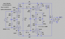
sorry for answering late. Here are the schematics:
Amp, one channel
PSU, for both channels
BTW, I used a tube rectifier just for the fun/optics of it ...
Regards,
Tom
sorry for answering late. Here are the schematics:
Amp, one channel
PSU, for both channels
BTW, I used a tube rectifier just for the fun/optics of it ...
Regards,
Tom
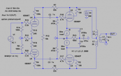
This is the variation on Yves circuit, but for input transformer. It can off course be optimized for ECL 82 or ECL86. No need for global feedback as long as you go Class-A.
If you want go Class-AB there has to be capacitors from the cathodes to ground and another working point. And NFB......
If you want go Class-AB there has to be capacitors from the cathodes to ground and another working point. And NFB......
Attachments
revintage said:
If you want go Class-AB there has to be capacitors from the cathodes to ground and another working point. And NFB......
There are better solutions for Class AB1 (triode connected) where you don't need any Fb as well. The simplest is using a classic cathodyne splitter. As Jaap mentioned before, an ECC40 will work nicely in such application. With 250V supply voltage you can get 2x18V RMS with 1% THD. This much more than needed (7-8V RMS typically).
Accordingly the distortion will be proportionally lower. You can estimate approx. 0.3% THD only from the front-end (just before the clipping). And this will be practically 2nd harmonic only and very probably you can sort-out some way to cancel it out.
The splitter can be directly coupled to the voltage amplifier or RC-coupled. I prefer the latter because you have more freedom for the design, the tube experiences less "suffering" when allowed for auto-biasing and, IMO, this is reflected on the sound.
Cheers,
45
Hey 45,
Think you missunderstood. You are looking at the wrong end of the amp") .
.
There are no problems with distortion in the driver. All is in the output. And as it is a PP 3H dominates.
What happens when you go over from A to B, is that the load for the output tubes is doubled. Another driver or PI won´t help you.
Given Jaaps wish to have only two holes and ECL82s he already has the two triodes needed for both PI and drivers.
As you suggested 6S4S in PP would be nice ! The ECL82 amp without OPTs could even be used as driverstage.
Think you missunderstood. You are looking at the wrong end of the amp
. There are no problems with distortion in the driver. All is in the output. And as it is a PP 3H dominates.
What happens when you go over from A to B, is that the load for the output tubes is doubled. Another driver or PI won´t help you.
Given Jaaps wish to have only two holes and ECL82s he already has the two triodes needed for both PI and drivers.
As you suggested 6S4S in PP would be nice
! The ECL82 amp without OPTs could even be used as driverstage.This is the ECL82-version. without C5 you will get over 2W in pure Class-A. With C5 in place you probably will get almost 4W in AB. It sims very well with low THD until just before clipping. I have some doubts about the pentode model I use, will try to find another.
Attachments
Guys,
As you would guess this thread caught my eye.
I haven't done much for about a week - we are on our 5th day of greater than 42 degrees C (108 degrees F) in a row and it looks like we have 3 or 4 more days of it to go. Wednesday in fact got to 45.7C (118F). Not great weather for playing with tube amps.
The Circuit proposed at Post#1 has promise. I would echo comments of others about the input pot arrangement.
The circuit at post#22 (posted by Jaap) is really interesting. My view is that the cross coupling the balanced feedback like this should give a quite different harmonic distortion profile than the circuits returning the feedback to the same side diffamp anodes. I think it should be better at suppressing odd order harmonic distortions, a useful thing in any push pull amp (like whats done in a Citation II). Do you agree?
Lars (revintage) - re: schematic at post #45,
At your convenience (and if you can be bothered) can you look at the effect on odd order harmonic distortion of using MUCH lower values of R18 (currently 100K). I am suggesting a value of around 30 to 50 Ohms.
Cheers,
Ian
Hi Ian,
Have done it before and just did it again !
There is no difference at low levels!
Near clipping the difference between the 39ohm and the 100k version is that the 100k gets a trifle higher H2 and H3 barely visible lower.
When shorting R18 H2 gets even lower and H3 higher. Points in the wrong direction doesn´t it?
Will dig deeper into this eventual tweak favoured by AW. But remember this is sims and the differances are small. If it sounds better, use it!
Have done it before and just did it again
!There is no difference at low levels!
Near clipping the difference between the 39ohm and the 100k version is that the 100k gets a trifle higher H2 and H3 barely visible lower.
When shorting R18 H2 gets even lower and H3 higher. Points in the wrong direction doesn´t it?
Will dig deeper into this eventual tweak favoured by AW. But remember this is sims and the differances are small. If it sounds better, use it!
Lars,
Thanks - That "stacks up" with what I found in listening ONLY tests using the fixed bias version of the Baby Huey.
I tried a common 39 Ohms in the cathodes. that is, individual 10 Ohms for current monitoring and then a common 39 Ohms to 0V. I set bias with the 39 Ohms shorted and then listened with the 39 Ohms shorted and with it in place (short removed) - just accepting that I also got a bias reduction when the short was removed. Based upon just listening tests I eventually deleted the common 39 Ohms. I thought that with the common 39 Ohms in place the amp lost some impact and slam (although it may have been as a result of the reduced idle currents (about 20%) with the 39 Ohms in place).
I don't have distortion measuring gear at the moment but am in the process of restoring an ancient (1961) Hewlett Packard 302A Wave Analyzer. This thing is a tunable (20Hz to 50kHz) precision voltage meter with an 8Hz pass band and 75dB out of band rejection. Won't be ideal but its a start. It uses a balanced modulator, 100kHz IF frequency and XTAL based IF Filters. Might even design a cheap modern version of it for DIY'er use one day.
Cheers,
Ian
Allan Wright recommends the approach of lowering R18 from a high value (100K) to a low value. In my version of this amp I have it set high at 1Meg and it works fine. On my other amps I went down from 1Meg to 300R and noticed a slight improvement in smoothness. Barely noticable though. I think you have to be careful of hearing what you want with this type of marginal tweak.
Shoog
Shoog
revintage said:Hey 45,
Think you missunderstood. You are looking at the wrong end of the amp
There are no problems with distortion in the driver. All is in the output. And as it is a PP 3H dominates.
What happens when you go over from A to B, is that the load for the output tubes is doubled. Another driver or PI won�t help you.
No revintage, my driver description was just to tell that, as you say, THD will come anyway from the output stage even if you go for the simple cathodyne. This driver is simple, works great and you don't need any input tranformer which, if not of high quality, will have a negative influence on the sound.
The transition from class A to B is very broad with vacuum tubes if the idle current is high enough (i.e. 300V/25mA with 5K a-a load for the EL84's) and you will be not able to see any anomaly in the THD as function of output if things are well done.
In fact, if the idle current is not low, in many RCA datasheets an amplifier delivering a RMS current identical to its idle current is still considered class A.
In theory, instead, it should be class A until the output peak current equals the idle current......
I never trust simulators when working out the THD, the models they use (indipendently of their accuracy) are always based on average specs.
Cheers,
45
gingertube said:Guys,
The circuit at post#22 (posted by Jaap) is really interesting. My view is that the cross coupling the balanced feedback like this should give a quite different harmonic distortion profile than the circuits returning the feedback to the same side diffamp anodes. I think it should be better at suppressing odd order harmonic distortions, a useful thing in any push pull amp (like whats done in a Citation II). Do you agree?
It is good if you don't kill the odd to get the even!
At low-to-medium levels the perfect push-pull must not have any distortion, the best real one 3rd harmonic only.
Odd harmonics, obiviously, should be as low as possible and if they are so, you will not hear any coloration on the sound. It will be just natural.
If the valves have good linearity in triode connection, in my experience, any kind of Fb is not necessary....unless you are going for class B!
Cheers,
45
I never trust simulators when working out the THD, the models they use (indipendently of their accuracy) are always based on average specs.
Same, same when you sit with your slide-ruler, pencil, paper and a Ua/Ia-diagram: They are all based on average specs!
Same maths, but higher accuracy, IF the models mirrors the diagram
. You still just need indications, not exact figures!If we leave calculations behind, IMHO pure Class-A still rules soundwise.
Still Jaap wants it done with 2 triodes and 2 pentodes in only 2 envelopes.
So either going for balanced with input transformer or going for LTP with CCS would be the obvious choices as they are easy to convert between each other.
If the valves have good linearity in triode connection, in my experience, any kind of Fb is not necessary....unless you are going for class B!
Well spoken
! Especially global NFB is a NoNo when dealing with transformers.Also, as you indicate, don´t mind 2H. 3H(and the higher even) is the enemy
 !
! But an evenly falling overtonespectra seems to do less harm soundwise.
revintage said:
Same, same when you sit with your slide-ruler, pencil, paper and a Ua/Ia-diagram: They are all based on average specs!
Same maths, but higher accuracy, IF the models mirrors the diagram
If we leave calculations behind, IMHO pure Class-A still rules soundwise.
No, my observation is based on the real thing. Triode connected EL84's, biased at 300V/25mA with 5K OPT, give 5W and it is still Class A for me because it sounds as class A.....please compare the sound to the "equivalent" EL84 PSE.
revintage said:
Still Jaap wants it done with 2 triodes and 2 pentodes in only 2 envelopes.
It doesn't seem to me......that is just one option. Anyway you can do that "with 2 triodes and 2 pentodes in only 2 envelopes " , as well using a cathodyne.
revintage said:
So either going for balanced with input transformer or going for LTP with CCS would be the obvious choices as they are easy to convert between each other.
In this case (i.e. small amp with sensitive output devices) they are so obvious that I wouldn't go for either!
This is just the situation where the cathodyne really works at its best.
Cheers
45
No, my observation is based on the real thing. Triode connected EL84's, biased at 300V/25mA with 5K OPT, give 5W and it is still Class A for me because it sounds as class A.....please compare the sound to the "equivalent" EL84 PSE.
So we are not talking measurements, we are talking listening impressions?
I can agree that, when using for so small tubes, going for Class- AB, as you suggest, is to be prefered.
This is just the best situation where the cathodyne really works best.
Nothing wrong with the Concertina, but adding it at the input also normally means adding three caps. Seems you recommend a Williamson driver without input tube
. In my world a good LL(or other hiQ) transformer is the way to go.
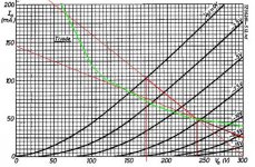
Edit: Added curves to show what happens with 300V/5k/25mA. Pmax=7W, Pclass-A=1W. Also from 1W and upwards the tubes are over Pamax with 16W at clipping. These are very course figures, just an indication.
Attachments
What you may not see in a sim is that with a lowish value of this R18 you get a LOT more power on signal peaks, the amp just sounds a lot more powerful.
That's the only reason I use a lowish value, otherwise the circuit more closely appoximates differential operation with a high value, just low enough so the big elco's get biased OK.
Using this whole concept on a rebuild 70 watt Chinese amp - sounds suprisingly good. But without the NFB. I used anode/anode NFB for years but finally prefer the sound without it.
Regards, Allen
revintage said:
So we are not talking measurements, we are talking listening impressions?
I can agree that, when using for so small tubes, going for Class- AB, as you suggest, is to be prefered.
Both of them.
The simulator measurements are never the real ones. They are almost always not reliable when approching the max output.
revintage said:
Nothing wrong with the Concertina, but adding it at the input also normally means adding three caps. Seems you recommend a Williamson driver without input tube
In my world a good LL(or other hiQ) transformer is the way to go.
Single ended input + direct coupled (or RC-coupled) cathodyne which drives the output.
You need 2 or 3 caps depending on which way you go.
Good quality caps, especially in this application where the signal level are low, simply sound transparent. I always use the SCR MPK 630V.
A good thing would be using a fixed-bias instead of a common cathode resistor because, with both cathodes grounded, you could balance dynamically the amp (i.e. with a signal and a spectrum analyzer).
This has nothing to do with DC current balance, rather the output tranformer should be able to withstand some little unbalance (5-10% of the single valve idle current is enough).
You ground cathodes through a small value linear pot (in this case 50 ohms should be enough), then once you get the best dynamic balance (i.e. minimum distortion) you measure the values on the pot and replace it with fixed resistors.
Cheers,
45
- Status
- This old topic is closed. If you want to reopen this topic, contact a moderator using the "Report Post" button.
- Home
- Amplifiers
- Tubes / Valves
- Could this become a Baby Huey killer ?