And what about this one for the volume control? http://www.raleighaudio.com/figure_18.htm
That looks like a very nice solution.
Shoog
Jaap said:This is also a kind of feedback that i intend to try.
Why is the designer using the 27K resistor at the input ?
An externally hosted image should be here but it was not working when we last tested it.


Hi Jaap,
I did something similar to your ECL86 headphone amp schematic (except for the input xfrmr) using PCL84 / 15DQ8 with triode-strapped pentode sections as an example of using "cheap TV"-tubes for my ETF06 lecture.
Actually, it is a real but flea power (1W/ch) triode(d) PP pure class A amp able to drive small speakers. It uses additional dummy loads when plugging in a headphone, cutting spkr outputs off. In headphone mode it is able to drive anything from 20 ohms to what you want.
This one won several local shootouts against Jones/Cavalli WCF type and also 6AS7/6080 "big CF" type headphone amps, especially clearly when low-Z headphones like my Sennheiser HD595 ones were used. So I suppose you are on the right track, although trioded ECL82 PP certainly is a brute overkill. Anyway, you always can use it as a dual-purpose amp to drive smallish speakers, too ....
I can make the schematics available (again), if of interest.
Regards,
Tom
Attachments
Jaap said:This is also a kind of feedback that i intend to try.
Why is the designer using the 27K resistor at the input ?
IMO it is a very good idea and works nicelyl with all high Gm pentodes lile PCL82/86, EL84, EL86......
In the circuit above, the Fb should be approx. 3dB (output stage in triode connection) and you could get 5W with very low distortion (approx. 1%!!).
The input impedance is practically 24.5K however I don't think it is a problem for any good preamp: for 5W output it should require 1.3-1.4V only.
That is the only "downside", IMO it works much better than any Fb solution which makes any use of the OPT. Basically the amp is more stable.
Cheers,
45
Shoog said:The input bias should be about 0.8V and since there is no cathode feedback anything more than that would overload the input and reintroduce some harshness to the sound.
Shoog
Shoog I always prefer the cathodyne splitter and overload is never a problem with PCL82's.
In that case the plate-grid feedback would be limited to the output stage.
You will need another stage to drive the output tubes given the low input impedance but they could be pentode-connected for 10W power output.
The driver could be a simple RC-coupled SS source follower.
I have made a PSE using the above solution and it works great.
For pentode connection you will need more Fb, however the driving voltage is only 13V RMS and the input triode can swing up to 25V RMS with a bit more than 1% distortion if R-loaded and substancially less if CCS loaded.
Cheers,
45
Re: schematics
Ok Jaap, give some time.....I don't have and don't use simulators or other circuit design stuff so I have to do it with powerpoint!
Basically if you go for RC-coupling and self-bias for the output stage you will need approx. 255-260V (depending on drops) in order to have 250V voltage supply (19-20V will drop on the cathode resistor).
With more than 250V at input you can use 1,5K cathode resistor and 120K for the anode and will get a bias around 1.4V and a gain of approx. 45. The overall gain, considering the splitter and the source follower will be around 36.
So you can apply up to 6db plate-grid Fb without overloading the input.
The splitter is RC-coupled to the input mainly because you can better set the quiescent point for your purpose.
The driver can be a JFET source follower (80-100V JET's are good).
Each stage is RC-coupled and someone would not like it, but IMO it sounds.
Here the voltage swings are modest. Especially if you use 630V good quality caps like the SCR MPK, they will sound transparent....
Cheers,
45
Jaap said:would be very nice
Ok Jaap, give some time.....I don't have and don't use simulators or other circuit design stuff so I have to do it with powerpoint!
Basically if you go for RC-coupling and self-bias for the output stage you will need approx. 255-260V (depending on drops) in order to have 250V voltage supply (19-20V will drop on the cathode resistor).
With more than 250V at input you can use 1,5K cathode resistor and 120K for the anode and will get a bias around 1.4V and a gain of approx. 45. The overall gain, considering the splitter and the source follower will be around 36.
So you can apply up to 6db plate-grid Fb without overloading the input.
The splitter is RC-coupled to the input mainly because you can better set the quiescent point for your purpose.
The driver can be a JFET source follower (80-100V JET's are good).
Each stage is RC-coupled and someone would not like it, but IMO it sounds.
Here the voltage swings are modest. Especially if you use 630V good quality caps like the SCR MPK, they will sound transparent....
Cheers,
45
Jaap said:The question is, can it be bettered/optimized ? It sounds already very good as it is.
One suggestion: if you're going to run pentode finals, then I'd definitely want to include active screen voltage regulation. Pentodes operate best with a stiff screen supply, and especially one operating into as low an AC impedance as possible.
That's what I did for two designs running pentode finals.
Also, move your volume control to the primary side of the input xfmr. That way, you won't need ganged pots.
I am going to experiment further, thanks for all the suggestions so far. Keep posting 
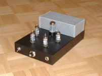
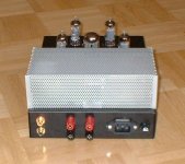
In the meantime I remembered that I still have a long time unused EL84 amp in the closet: inputtransformer => 2SK30 => stc style power stage. I fired it up and I must say that it sounds very good.
I don't have a clue how it works (most people don't I think) but this little amp is a killer. This kind of stc topology started in Japan with the 6BM8 tube. So I think I cannot escape in trying this too in the future.
Attachments
Jaap said:I am going to experiment further, thanks for all the suggestions so far. Keep posting
In the meantime I remembered that I still have a long time unused EL84 amp in the closet: inputtransformer => 2SK30 => stc style power stage. I fired it up and I must say that it sounds very good.
I don't have a clue how it works (most people don't I think) but this little amp is a killer. This kind of stc topology started in Japan with the 6BM8 tube. So I think I cannot escape in trying this too in the future.
With the EL84 you will have more freedom for the input stage, however you will need at least 3 valves for each channel.
Like Miles Power, I also recommend a regulated DC supply for the screen grids of the output devices.
In the above schematics you can save quite some money using a JET input splitter. The cathodine splitter (and its SS equivalent), IMO, is the best sounding electronic splitter. The two phases will be perfectly balanced as soon as the two loads are the same.
Differences in amplitude have nothing to do with output impedances which are not those derived for the case in which you take one output per time. The two outputs, in fact, have approx. 0.9 gain like a cathode follower......
After the splitter you can just put a 6922 mu-follower for each side and it will drive happily even 20K, given the low swing requirement of the EL84 and 230-240V supply.
20K is the impedance given by the grid-to-plate network basically: 22K in series with the decoupling cap and then 150K + C to the plate (then you also have 1K grid stopper, 270K to ground).
In parallel single ended, you don't need SS devices. It would be a plain 2-stage amp: 6922 mu-Follower + 2xEL84 in parallel. With the above grid-to plate Fb you will get approx. 9W with 2-3% THD and a damping factor of 4 or better!!
Cheers,
45
Hi Jaap,
From your first post I understand you want to build a simple but good amp with only two tubes and input transformer.
This is a great idea. If you use ECL86 instead together with the local feedback of Yves circuit you can build a really good one.
Triodestrap the tubes and run them in Class AB at 300V. You will then get 5W max with up to 3W in Class A. You can also skip the input CCS as you run transformer in, balanced without total NFB.
I have evaluated the circuit in LTSPice and it looks promising. I used EL84 as there is no available model for E(C)L86 that can be considered as a "mini-EL84".
I have also calculated Pout with the help of my www.revintage.se/PPABAMP.xls using the triode-curves for ECL86 that Tom Schlangen(Tubes4e4) kindly provided.
Input sensitivity will be ca 0,3V.
As Shoog recommended you can use mains toroids as OPTs if you don´t already have them. The only thing needed is double CCSs at the output tubes as balancing the currents is crucial.
I am at the moment planning a mini-amp as I have lots of NOS Tungsram ECL86 together with Talema 30W 2*115:2*6V (ca 9k:8ohm with 6,8V (no load) in parallell) and LL1544.
thanks again (all of you) for the interesting suggestions, i will certainly look into it.
I chose the ecl82/6bm8 because I have some (4 unused Telefunken and some Philips ) and two rather good OPT's which were made for them. Are you gentlemen suggesting the ecl86 for better sound or for more power ? I suppose that I can use the same OPT with ecl86.
I do not like Fet inputs because matching is a problem. The regulated screen supply is certainly on my list. And I have also some ecc40's (= e80cc) on the waiting line to put in a cathodyne splitter in some amp some day. But for this one I have promised myself to stick to two holes in the chassis. That doesn't mean that i cannot put some mosfets somewhere if this helps in finding the holy grail with a small two tube amp.
For some reason I like fiddling with tubes as ecl82/86 and el84 more than trying to get good sound out of 300B's.
I saw somewhere EL803 tubes, is a better version of el83. Also a nice candidate in this class of tubes I suppose (?)
I chose the ecl82/6bm8 because I have some (4 unused Telefunken and some Philips
) and two rather good OPT's which were made for them. Are you gentlemen suggesting the ecl86 for better sound or for more power ? I suppose that I can use the same OPT with ecl86.I do not like Fet inputs because matching is a problem. The regulated screen supply is certainly on my list. And I have also some ecc40's (= e80cc) on the waiting line to put in a cathodyne splitter in some amp some day. But for this one I have promised myself to stick to two holes in the chassis. That doesn't mean that i cannot put some mosfets somewhere if this helps in finding the holy grail with a small two tube amp.
For some reason I like fiddling with tubes as ecl82/86 and el84 more than trying to get good sound out of 300B's.
I saw somewhere EL803 tubes, is a better version of el83. Also a nice candidate in this class of tubes I suppose (?)
What is the Ra-a of your OPTs? Maybe to low for ECL86.
I can adopt the sim I have done as I have the models for 6BM8.
Stick with the transformer, it is the best PI you can get!
EL83 looks like a real minikiller when triode-strapped, with high mu, Gm and low Rp. 25, 13,5mA/V, 1,8kohm, 9W.
I can adopt the sim I have done as I have the models for 6BM8.
Stick with the transformer, it is the best PI you can get!
EL83 looks like a real minikiller when triode-strapped, with high mu, Gm and low Rp. 25, 13,5mA/V, 1,8kohm, 9W.
- Status
- This old topic is closed. If you want to reopen this topic, contact a moderator using the "Report Post" button.
- Home
- Amplifiers
- Tubes / Valves
- Could this become a Baby Huey killer ?