You can dig up either mine or MJK's by searching the forum.
One topology calling it FETron, and the other FETrode...
You could find either starting a search with "Schade"
What all these partial feedback share in common, is an odd
connect the dots puzzle that results in an equivalent Triode.
O.H.Schade of RCA first proposed this eqivalency long ago.
It wasn't a comment that implied FETs be used as the front
end of Jaap's project, though they could. Was more intended
to illustrate one very real reason why Shoog's suggestion of
a Pentode for this duty might work so well. The impedance of
its plate hardly varies at all with amplitude or frequency.
But then again, neither does a cathode follower with a big
series resistor after the output... Either could drive a plate
follower in Schade's partial feedback scheme.
This type of Triode emulator shows up again and again,
with hardly anyone realizing the significance. For example,
certain earlier incarnations of Nelson Pass' all solid state
Zen. Though you'd never get him to admit he'd used any
of Schade's techniques for emulating a Triode. This same
wheel is constantly being re-invented on both sides of the
sand/glass curtain.
I'm just callin a Schade a Schade.
And of course, the essence of Schade's partial feedback is that
it is proportional to Voltage from the plate. And as such it lowers
output impedance as seen at the plate. And linearizes Voltage
toward a constant Mu at the expense of control over current.
To differentiate it from the more common form of partial feedback
below the cathode, source, or emitter. A feedback proportional to
current. Serves to increase output impedance seen at the anode
terminal. And linearizes current toward a constant Gm at expense
of control over Voltage.
Pete Millett's sight I think it was???
Chapter entitled "Beam Power Tubes". Filed under RCA.
http://www.pmillett.com/tube_data.htm
Chapter entitled "Beam Power Tubes". Filed under RCA.
http://www.pmillett.com/tube_data.htm
Guys,
Some more comments based upon 2 years of Baby Huey experiments and results.
If you are using that "partial" - lets call it "balanced shunt" feedback from the output tube anodes then you need that cross coupling resistor. IT does two things for you. It gives a self balancing action BUT most importantly it reduces the feedback level to something which can be managed by the diffamp. With out it you will grossly overloading the diff amp expecting it to swing just too much current.
You can think of this in 2 ways:
1) The feedback signal at the other end of that anode load resistor is anti-phase to the swing you have to develop at the anode to drive the output tube grids. These two voltages add to give you the voltage you need to develop across that anode load resistor and so that increases the amount of current you have to swing through it.
2) Another way of thinking of that is that the anti-phase voltage from the output tube anodes causes an "anti-bootstrap" effect on the value of that anode load resistor. That is 220K with 6dB of feedback applied will make that resistor look like a 110K load to the diffamp tube.
The self balancing is also important - it is my contention that everything you do to a push pull amp to improve symmetry (balance) improves the sound.
All off my experiments have shown that about 6dB is the most sonically pleasing amount of feedback - you can run more but above about 12 dB the amp ends up sounding very solid state'ish (Cold, Sterile and Boring).
The Baby Huey scheme also gives one additional benefit - since there will be a virtual earth at the centre (depending upon balance) of that cross coupling resistor it provides a consistent and low source impedance for the feedback voltage.
The feedback voltage will be divided by the anode load and the rp of the tube. So HIGH rp is indicated for the diff amp triodes. The 6BM8 (ECL82) is not as good in this respect as a 6GW8 (ECL86). This is why I used a 12AX7 in the Baby Huey.
One possible good solution to the lower rp of the 6BM8 triode is to use a cascode diffamp with jfets on the bottom and the 6BM8 triodes on top. That will give a high composite rp.
High Rg1 value for the output pentode is also indicated for the same (voltage division of the feedback) reason. The 6BM8 is good in this respect, it tolerates high values of Rg1 well.
A way to use very high (say 1 Meg) Rg1 values is to follow the lead of Lars in his circuit at post #82 and use bias servo(s). I'd be incline to use one for each tube with a common reference setting.
There is another thing to worry about with output anode to driver anode feedback of this type (its effectively output tube anode to output tube grid as far as AC is concerned). The feedback resistor (which is the diffamp anode load) is effectively (AC wise) in parallel with the Miller Capcitance of the Output tube. That puts a definite upper limit on the size of that resistor. Go to high in value and you loose high frequencies. That upper limit will be much lower with the output tube in Triode Mode (since Miller Capacitance is higher).
The way to cope with that is to insert a MOSFET source follower, on each side, AC coupled from the diffamp grids and direct coupled to the output tube grids with fixed bias applied at the mosfet gate.
I haven't done a full SLCF treatment BUT I did change the MOSFEt Source follower to have a current source load. That (as AW says) gave a real lift in performance so I tend to believe that adding the boostrap top device (to complete the SLCF treatment by putting the follower into constant voltage mode) would also be of benefit.
Playing with all of these things over several years has lead to the Baby Huey circuits posted on its thread.
Do I think you can KILL the Baby Huey - you bet
Do I think anything posted so far is going to do it - No Way, but there is certainly food for though amongst those posts and a few of them may well lead to a Huey Killer.
I can add some more "general rabitting" about diffamp balance and the source of distortions and stuff if you like but thought this was enough for now.
Cheers,
Ian
-As he dons his flameproof underwear - na! to hell with it, as he dons his tee shirt with the bullseye target.
P.S. Screwing Up should be a learning experience BUT it can only be that if you tell me when I'm wrong.
gingertube said:Guys,
Some more comments based upon 2 years of Baby Huey experiments and results.
One possible good solution to the lower rp of the 6BM8 triode is to use a cascode diffamp with jfets on the bottom and the 6BM8 triodes on top. That will give a high composite rp.
There is another thing to worry about with output anode to driver anode feedback of this type (its effectively output tube anode to output tube grid as far as AC is concerned). The feedback resistor (which is the diffamp anode load) is effectively (AC wise) in parallel with the Miller Capcitance of the Output tube. That puts a definite upper limit on the size of that resistor. Go to high in value and you loose high frequencies. That upper limit will be much lower with the output tube in Triode Mode (since Miller Capacitance is higher).
The way to cope with that is to insert a MOSFET source follower, on each side, AC coupled from the diffamp grids and direct coupled to the output tube grids with fixed bias applied at the mosfet gate.
I haven't done a full SLCF treatment BUT I did change the MOSFEt Source follower to have a current source load. That (as AW says) gave a real lift in performance so I tend to believe that adding the boostrap top device (to complete the SLCF treatment by putting the follower into constant voltage mode) would also be of benefit.
Now it is getting very interesting: the hedge circuit (with a jfet at the bottom). I tried the hedge circuit in the implementation of AW (amp with el34PP) and it sounded outstanding. Perhaps the only thing that would sound a bit better is the Tabor.
I saw an article in Glass Audio 1994-2 (author Denzil Danner) who tries to better the hedge circuit. As far as I understand he places a current source on top of the cascodes (he uses a tube) with good results. He has no CCS in the tail but uses a psu with -150 volt. At the end of the article he says: "It is cheating, but a transistor current source for the differential amp cathode impedance avoids a lot of trouble and expense. FET current sources (on top) are also a possibility".
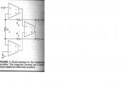
Another interesting article is from Scott Reynolds in Glass Audio 1996-8. He presents an differential amp for electret headphones with an interesting topology (see picture).
I think it resembles the baby huey in the feedback arrangment. The first gainblocks (12ax7) are in his design no cascodes but LTP's with again a negative powersupply (-275 volt).
If you change that to cascodes and you change the last gainblock (original 6sn7GTB) to a mosfet source follower you have the proposal of Gingertube (?).
Attachments
Great post Ian,
I knew this cross coupled "balanced shunt" Resistor had a significant role in the Baby Huey but couldn't have explained the details as you have.
So does it simulate accurately? Because someone here decided to drop this R as it raised the THD, AFAIR.
Maybe your post will encourage more investigation into this particular aspect! It's a pity that this thread got sidetracked & didn't pick up on your leads.
Ian, you suggested that Jaaps schematic in post #22 showing a different cross coupling (attached) could reduced odd-order harmonics - a useful attribute in a PP amp. I don't see the plate to plate feedback here - I guess there doesn't have to be one but can you explain more?
Attachments
The ground reference can come from the driver stage cathode resistor, and this takes the place of the cross coupling resistor.
i would say that the reason the THD rises as the Plate to Plate feedback increases is because the input triode requires more input signal to generate the same output level. In a normal gNFB amp the feedback is applied to the cathode of the driver and so effectively reduces the size of the signal arriving at the grid by moving the cathode in the oposite direction. In the case of the Partial feedback arrangement the feedback reduces gain at the plate and there is no effect on the input signal and so you simply need to apply a bigger signal to the grid to get the same output. Eventually you reach your bias point and start into positive bias territory which starts to draw grid current and that is where your increased THD distortion is coming from.
So in order to pull this off you need a driver tube with plenty of headroom - which the ECL82 most definately is not, so we start overdriving the driver and distortion climbs. Unfortunately that is the triode we are stuck with so we have to live with it and minimise the problem.
Hence in my design we are stepping down the input signal and leaving plenty of gain at he output.
Hope that helps.
Shoog
Shoog said:The ground reference can come from the driver stage cathode resistor, and this takes the place of the cross coupling resistor.
AC ground (in the middle of the cross resistor), for reference by
the Schade partial feedback network. Equally as valid as a real
DC ground for this purpose. Same exact thing as seen by the
driver stage cathode resistors, only different...
-------------------------------------------
This design might appear to break from local feedback, and take
the GNF approach backward two stages. But coupling between
stages is DC, so they behave almost like one. And the feedback
loop wraps around only one reactive phase shift. Other than
what wires might pick up, its still very "local-ish".
I suppose that if the front end is a LTP with shared resistor it probably functions as a common shunt, but I'm not entirely certain.
It maybe a good excuse for not replacing the tail with a CCS. Though having said that the Tabor has neither the shunt or the cathode resistor - rather a CCS. I can only think it gets its ground reference from the output stage power supply !!!
Shoog
It maybe a good excuse for not replacing the tail with a CCS. Though having said that the Tabor has neither the shunt or the cathode resistor - rather a CCS. I can only think it gets its ground reference from the output stage power supply !!!
Shoog
If the input duty is assumed by Triodes, the addition of any
unbypassed cathode resistor increases the plate's dynamic
resistance, and linearizes Gm for all orders of distortion.
But you don't need a higher dynamic resistance, only a flat
one. As the leak simply becomes part of the lower resistor
in the feedback divider. And long tail pairing also linearizes
Gm, at least in the even orders. With or without individual
cathode resistors.
If input duty is assumed by Pentodes or Sand, such source
resistors and/or tail pairing may still serve to linearize Gm.
But impedance at the anodes ain't likely to get any higher
than an already sandy flat line...
In this part of the circuit, a flat anode impedance might be
exactly the right thing to tickle the Schaded Plate follower
networks wrapped around the output Pentodes. But again,
you don't want to degrade the gain of the input tubes any
more than necessary to get the drive impedances stable.
I keep seeing advise to regulate the screens, but I keep finding experienced designers advising to simply tie the PP screens together and reference them to +B via a dropping resistor. Peter Millet claims that this produces lower THD distortion than VR tubes, smoothing cap or regulation.
Gary Pimm recommends the same approach but with reasonably high screen resistors (10K) in series with each screen on the drivers. He claims that this introduces a feedback mechanism and avoids introducing hum into the pentode.
To me these approaches seem reasonable, if you consider that screen current is largely linear and goes up and down in the opposite direct in a PP pair, then the overall screen current is constant for the pair and the screens are working rather like a LTP with all the advantages that brings.
My experience is that this approach works. Anyone have any thoughts on this.
Shoog
I keep seeing advise to regulate the screens, but I keep finding experienced designers advising to simply tie the PP screens together and reference them to +B via a dropping resistor.
Both can be good. The main thing you want to avoid is having RC time constants on g2.
When regulating g2, I've had the best results when the cathode-bias resistor is left un-bypassed and un-shared to add some local degenerative feedback. G2 regulation is pretty much the only option to get good sound from an SE Pentode. It is ok to add a resistor in series with the screen as well.
With the shared dropping resistor method, you will find that the Vg2 (DC) will shift depending upon how much signal is applied because of non-linearity. It will in turn shift the quiescent plate voltage some, when the signal strength changes, which happens continuously in music.
When there is no RC time constant on g2, the shift happens instantaneously, so it causes no problems(and can actually be beneficial sometimes). If there is an RC time constant, the shift is delayed. This shift delay will completely ruin the attack characteristics of the amplifier. It also exhibits some other strange transient behavior that will make the sound incredibly fatiguing.
I suspect tying g2's directly together could decrease THD, but increase IMD. Some separation is probably desired. Also, adding screen resistors on each pentode will add some local degenerative feedback. This could be really desirable if the pentodes cathodes are at AC ground potential. Gary's method probably gives good results, if you have the gain to spare. Just make sure Vg2 doesn't swing too low or your driver will clip pre-mature.
Thats extremely useful information.
I guessed it wouldn't work to well with SE, and I also suspect it wouldn't be as appropriate for amps designed for hard AB operation.
I may make a modification to my tabor amp to see if I get any slight improvement. At the moment I have both driver channels screens tied to one VR150 tube with resistance in each screen leg. Theis introduces a small amount of crosstalk. If I drop the series resistance on each leg and move the bulk of the resistance to the shared VR reference - hopefully this will reduce distortion and remove the crosstalk.
Cheers
shoog
I guessed it wouldn't work to well with SE, and I also suspect it wouldn't be as appropriate for amps designed for hard AB operation.
Very true.
Single ended and hard class AB-PP pretty much need screen regulation for best performance.
Class A PP opens up the shared dropping resistor option (of course regulation is still a viable option).
I'm not the kind of guy that typically advocates regulating. But the screens is one place where RC time constants can truly be evil.
- Status
- This old topic is closed. If you want to reopen this topic, contact a moderator using the "Report Post" button.
- Home
- Amplifiers
- Tubes / Valves
- Could this become a Baby Huey killer ?