"Nuts,no European equivalent!"
Sorry! I imagine most any of those old battery tubes with directly heated filaments would be quite linear too. Low gm being another key item. I just picked this one out of my junk box out of curiosity. It's odd dual pent. and pin limited configuration has no doubt contributed to its obscurity.
Re: Gordy
The two plates were wired together, and the two g1's were wired together. No way to separate the g2 between them.
I think one could just use one plate if you wanted to just use one section, but that would require biasing the other g1 negative enough to cut off current to the g2 in the unused section. I got some weird curves until I put them together completely because of g2 current from the other section. Two in parallel does at least double the gm to around 3000 at least at 4 mA.
I'll get some pentode curves together.
Last edited:
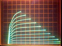
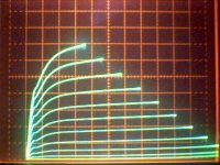
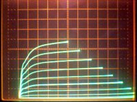
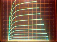
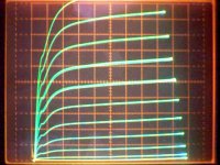
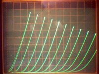
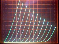
Here are some pentode curves for the 1E7G (single section)
Scales: 1.2 V per g1 step, 2 mA/div vert., 20 V/div horiz.
a) g2 at 135 V
b) g2 at 115 V
c) g2 at 95 V
d) g2 at 115 V both sections parallel
Scales: 1.2 V per g1 step, 2 mA/div vert., 20 V/div horiz.
a) g2 at 135 V
b) g2 at 115 V
c) g2 at 95 V
d) g2 at 115 V both sections parallel
Attachments
Last edited:
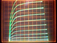
This is a comparison of section 1 and section 2 under identical conditions. (I may have gotten the 0 V g1 bias point a little off in the above post, since it shows a little more the 1/2 the max current of the paralleled sections post) The two sections are reasonably well matched, but not close enough for "matched" status. No idea if this is relevant to other bottles though.
Scales: 1.2 V per g1 step, 1 mA/div vert., 20 V/div horiz., g2 at 115V
a) pins 3,4 section
b) pins 5,6 section
Scales: 1.2 V per g1 step, 1 mA/div vert., 20 V/div horiz., g2 at 115V
a) pins 3,4 section
b) pins 5,6 section
Attachments
Last edited:
"What do you use for making these traces? "
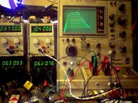
A Tektronix Type 576 Curve Tracer that I got off Ebay a while back. It's been modified to allow higher step voltage ranges for grid stepping. It originally comes with a max 2 V per step for FETs. I now have a knob to vary the scale up to 10X or 20 V per step for tubes. The step generator stayed the same, but I replaced the step amplifier with higher voltage transistors and the step amplifier's power supply got replaced. The knob is just a pot in the feedback loop for the step amplifier to change the gain. I also fixed up the test box to provide 2 separate screen voltages. Two external supplies get switched in depending on which DUT is selected. (Two position DUT switch for comparing devices) Couple other power supplies for filaments. See picture 1.
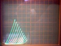
The other pictures are of a 6LQ8 pentode in triode mode. This is a cheap $1 video amp tube with a frame grid (21,000 gm). I was curious to see how much the curve tracer presentation scale affects one's assessment of tube linearity. Picture 2 is on the same (2ma/div, 20 V/div ) scale as used for the 1E7G tube. Picture 3 is using a more appropriate scale (power wise, a 5W tube so 10 mA/div, 50 V/div, well I'm super smoking the tube too in pic 4) for the 6LQ8, but the grid and plate V sweep is still set to the same as picture 1. Then picture 4 has the sweeps expanded out to use the full screen view range. Just curious to see the impression of linearity in each view. Looks to me like pictures 2 and 4 could be the same, I thought the linearity would look worse over a bigger range. Picture 5 is the 1E7G tube again for comparision. (The 6LQ8 scans are using .475 V per step g1 and the 1E7G scan is using 2 V per step g1)
A Tektronix Type 576 Curve Tracer that I got off Ebay a while back. It's been modified to allow higher step voltage ranges for grid stepping. It originally comes with a max 2 V per step for FETs. I now have a knob to vary the scale up to 10X or 20 V per step for tubes. The step generator stayed the same, but I replaced the step amplifier with higher voltage transistors and the step amplifier's power supply got replaced. The knob is just a pot in the feedback loop for the step amplifier to change the gain. I also fixed up the test box to provide 2 separate screen voltages. Two external supplies get switched in depending on which DUT is selected. (Two position DUT switch for comparing devices) Couple other power supplies for filaments. See picture 1.
The other pictures are of a 6LQ8 pentode in triode mode. This is a cheap $1 video amp tube with a frame grid (21,000 gm). I was curious to see how much the curve tracer presentation scale affects one's assessment of tube linearity. Picture 2 is on the same (2ma/div, 20 V/div ) scale as used for the 1E7G tube. Picture 3 is using a more appropriate scale (power wise, a 5W tube so 10 mA/div, 50 V/div, well I'm super smoking the tube too in pic 4) for the 6LQ8, but the grid and plate V sweep is still set to the same as picture 1. Then picture 4 has the sweeps expanded out to use the full screen view range. Just curious to see the impression of linearity in each view. Looks to me like pictures 2 and 4 could be the same, I thought the linearity would look worse over a bigger range. Picture 5 is the 1E7G tube again for comparision. (The 6LQ8 scans are using .475 V per step g1 and the 1E7G scan is using 2 V per step g1)
Attachments

Last edited:
Yes we know, but above about 2mA those curves really are equally spaced! So just stay out of the sub-2mA region.
If it is a triode it follows Child’s Law, otherwise known as the 3/2 (three halves) Power Law. Open any triode model in your favorite Spice program you find the 3/2 in the model. The curves get closer together as you move right to left across the graph. That is the best case. Vary the pitch of the grid and things get more pronounced. Also take a look at the plots posted in this thread the curves get straighter the higher you look on the graph. The straighter the curve gets my bet is that the current is far in excess of the do not exceed design center value on the data sheet.
Take a look here! Space charge - Wikipedia, the free encyclopedia
DT
All just for fun!
Childs Law: Ip=G(Vg+Vp/Mu)^1.5 = G(K)^1.5
You will notice that the Vg and Vp terms are within the 1.5 exponent term and so are linearly related to each other by K=Vg+Vp/Mu for constant current.
This is how the equal spacing of curves comes about at constant Ip or (hence) constant K (for a constant Mu). So the curves must be equally spaced at any constant current level for constant Mu.
Ie, one can trade off Mu*Vg volts for equal Vp volts anywhere and get the same current result.
What causes the actual tube curves to become non-equally spaced (at constant current) is the Island Effect, caused by proximity effects of individual grid wires casting electrostatic shadows on the cathode surface. This causes the typical leaning over effect on the curve set at high plate Vs.
Old low gm tubes (particularly DHT and DHP) have sufficient grid to cathode spacing to minimize this Island Effect. Later high gm tubes used closer grid to cathode spacing to maximize gm at the expense of linearity. To get a high linearity tube one needs to sacrifice gm by using greater grid to cathode spacing or use finer grid wire spacing to eliminate the shadow effects. Unfortunately, most of the later frame grid tubes also decreased the spacing as well to maximise gm rather than linearity.
Last edited:
If all the grid spacings are exactly equal, and you don't have some
paths of the triode pinch off before others... Remote cutoff makes
a triode lean over to the right, as strongest samples of the average
disappear from the set... No triode will ever be built with an exact
perfect match of cutoff for all possible internal paths.
Its averaging effect of many parallel triodes that behaves imperfect.
If you average 4 or more slightly different Childs law sets, only then
might one aproximate the behavior of the real triode. And experiment
with such averages makes me suspect that square law may hold more
truth than Child's ^1.5? Before averaging the taint of a diminishing set...
Operating at fixed current also prevents samples from dropping out
of the set and changing the average. Even the sloppiest of triodes,
at fixed current, Mu still behaves much like one would expect.
I don't know why this solved mystery should now be blamed upon
shadows? The island effect??? Hey boss, De-plane De-plane!!!
OK, not that island...
Last edited:
Yes.
Take a look at post #33. Picture #1 is a 6KR8 triode which has bad Island Effect heebie jeebies (gm 10400, large Mu variation). Picture #4 is a 6U9 which is a remote cutoff sicko. Just a more extreme variation of Mu than the Island Effect. A 6LY8 triode is similar in size to the 6KR8 triode, but is near constant Mu (and gm 1700).
http://scottbecker.net/tube/sheets/135/6/6KR8A.pdf
http://scottbecker.net/tube/sheets/135/6/6LY8.pdf
Last edited:
You will notice that the Vg and Vp terms are within the 1.5 exponent term and so are linearly related to each other by K=Vg+Vp/Mu for constant current.
This is how the equal spacing of curves comes about at constant Ip or (hence) constant K (for a constant Mu). So the curves must be equally spaced at any constant current level for constant Mu.
The graph of a tubes plate curves is if you will is a map of the weighted average of the electrical effects of the tubes internal geometry. Individual islands are not on the map, just their shadows.
Let’s call it an imaginary load line where a tube sees a constant current supply the “load line” is flat and has a slope of 0. In this condition gm and Rp variations are minimized as is mu variation. This is near the idealized triode. Now add a real AC connected load, pick your impedance. AC speaking the tube is in parallel with the AC load. Do the math, the operational load line has the slope of the connected load not 0. So much for your ideal triode.
DT
All just for fun!
So who's going to take a shot at the pic that Lars posted in message #50 ?
The max current on the scale is 87.5mA so it's surely a small power pentode of some kind. I don't know my Russian valves though (except 6P14P, and it ain't that!)
I have never known an EL84 triode to be anywhere near that linear! But I'd love to be wrong...Merlinb, to my inexperienced eyes it looks a little like EL84 ? Which would be 6P14P...

I´d say that it is a triode strapped 6e5p.
Congratulations Anders! I remember Bo once told me you knew every tube there was. Seems be true
- Status
- This old topic is closed. If you want to reopen this topic, contact a moderator using the "Report Post" button.
- Home
- Amplifiers
- Tubes / Valves
- Could this be a perfectly linear triode?