Very nice results obtained by you with this tube. I also tested an SE amplifier in class A2 but i couldn't find a pair for 100TH and i had to abandon the project but i still did a mono audition and i was very happy with the dynamics of this SEYeah, the 100TH exceeded my expectations by a good margin, and I love the way they look.
I'm guessing that pretty much any high-impedance triode will give similar results, though. The 826 did really well. I originally considered the topology after wondering if there wasn't an easy way of making a tube like an 811A perform better than a 300B.
I've been just hunting for bargains on high impedance tungsten-filament triodes on eBay. There are lots of types that don't seem to have much demand and can be bought for pretty cheap. The crazier they look, the better (I think).
Attachments
Hi SpreadSpectrum,
I'm following your results with alot of interest, as the idea is very smart.
What is the Zout of the amp with different tubes? I guess in any case something very near to the Rdc of the secondary.
I haven't measured Zout with the 100TH. It was 0.6 Ohm with the early experiments with the 6384 tube and 0.7 Ohm with the 826. The 6384 has about the same gm as a 6L6. These transmitting triodes are pretty low gm tubes and I think have about 2/3 the gm of a 6L6. These measurements are approximate as I'm injecting a signal into the output of the amp with a cheap signal generator, and the amp output is noisy. You are right that resistive losses account for about 5.5 Ohms of the Zout.
Resistive losses in the transformer have increased since I took those measurements (I bought some 35W ElectraPrint transformers, which probably have many more turns of wire than the Edcors) so I expect about 0.8 Ohms or so Zout now. Hopefully I can measure this weekend.
Very nice results obtained by you with this tube. I also tested an SE amplifier in class A2 but i couldn't find a pair for 100TH and i had to abandon the project but i still did a mono audition and i was very happy with the dynamics of this SE
That looks just like my Lewis and Kaufmann tube. It's too bad Russia never used 100TH in military applications or they would probably be cheap and plentiful today.
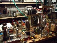
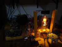
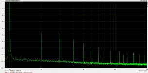
I got the 327A installed today and running. The 327A uses the 100T plate. Gain is slightly less than a 100TH, and it has a 110W filament  . The tube lights up extremely bright. It was designed for pulsed duty in a WW2 ship radar, so it must have needed a lot of peak emission to have a filament that dissipates more than the plate.
Sound was excellent. Sweet and effortless even at ear-bleeding volumes. A real pleasure to listen to. It topped out at 38.3W.
I'll attach the distortion measurements to the next post. Too many pictures for 1 post.
. The tube lights up extremely bright. It was designed for pulsed duty in a WW2 ship radar, so it must have needed a lot of peak emission to have a filament that dissipates more than the plate.Sound was excellent. Sweet and effortless even at ear-bleeding volumes. A real pleasure to listen to. It topped out at 38.3W.
I'll attach the distortion measurements to the next post. Too many pictures for 1 post.
Attachments
100mW: 0.014%
500mW: 0.019%
1W: 0.026%
2W: 0.038%
5W: 0.057%
10W: 0.056%
20W: 0.077%
30W: 0.14%
38.3W: 0.48%
Distortion was generally slightly higher than the 100TH, but very close.
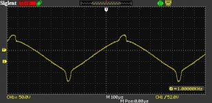
Grid waveform indicates that clipping is hitting both sides pretty symmetrically; a good balanced operating point.
500mW: 0.019%
1W: 0.026%
2W: 0.038%
5W: 0.057%
10W: 0.056%
20W: 0.077%
30W: 0.14%
38.3W: 0.48%
Distortion was generally slightly higher than the 100TH, but very close.
Grid waveform indicates that clipping is hitting both sides pretty symmetrically; a good balanced operating point.
Attachments
-
 Grid at Clip.jpg45.8 KB · Views: 95
 -
 38.3W.jpg274.8 KB · Views: 90
 -
 30W.jpg214.5 KB · Views: 86
 -
 20W.jpg211.9 KB · Views: 100
 -
 10W.jpg205.1 KB · Views: 99
 -
 5W.jpg206.3 KB · Views: 88
 -
 2W.jpg203.3 KB · Views: 74
 -
 1W.jpg196.5 KB · Views: 92
 -
 500mW.jpg199.6 KB · Views: 192
 -
 100mW.jpg200 KB · Views: 211
You are right that resistive losses account for about 5.5 Ohms of the Zout.
I made a typo in this post above, I meant 0.55 Ohms.
I measured Zout with the 100TH and got 0.56 Ohms, but I don't believe that. That's less than the DCR of the secondary. I've made a measurement error somewhere. However, I do think I've got a DF that is at least greather than 10.
Thanks!
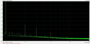
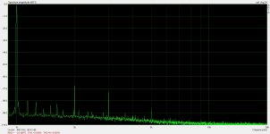
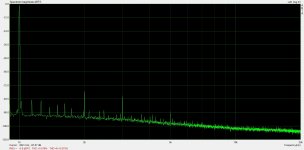
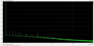
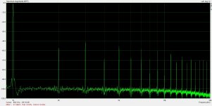
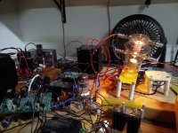
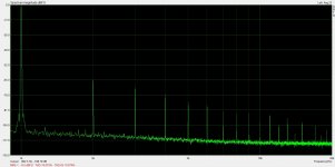
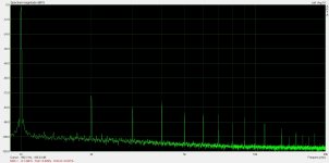
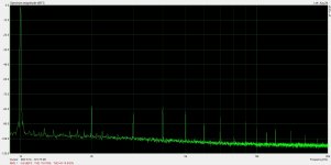
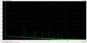
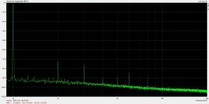
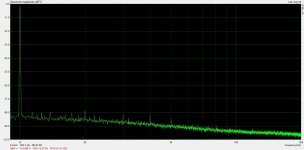
I got a VT-127 into the amp today and got it tested. The VT-127 is also a 100T variant used in WW2 ship radar. It is a lower mu tube than the 327A and has a 55W filament. Mu is about equal to a 100TL.
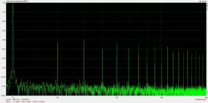
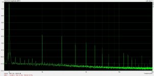
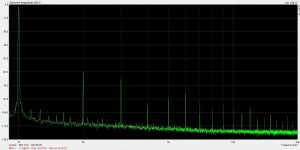
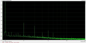
Attached are results. Here is a distortion summary:
100mW: 0.012%
500mW: 0.026%
1W: 0.025%
2W: 0.016%
5W: 0.028%
10W: 0.072%
20W: 0.15%
30W: 0.26%
42.5W: 0.53%
I noticed I had more high-order harmonics in the results. I'm speculating that crossing the Vg=0 line is generating this. We start crossing at about 500mW with this tube since it is biased at +10V on the grid and is lower gain than the other tubes. The higher mu tubes were biased at more like +35V and they have more gain, so we don't start crossing Vg=0 until much higher power levels. It makes me wonder if the best results wouldn't be with a really high mu triode like 811A. The grid wouldn't go negative on that one until just before clipping.
The dip in distortion between 1 and 5W was kind of strange as well. Not sure how to explain that. Also, I got a bit more power out of this one. Maybe I just pushed it a bit harder. I'm kind of just looking for where the grid waveform starts getting spikes and stopping there.
I got a VT-127 into the amp today and got it tested. The VT-127 is also a 100T variant used in WW2 ship radar. It is a lower mu tube than the 327A and has a 55W filament. Mu is about equal to a 100TL.
Attached are results. Here is a distortion summary:
100mW: 0.012%
500mW: 0.026%
1W: 0.025%
2W: 0.016%
5W: 0.028%
10W: 0.072%
20W: 0.15%
30W: 0.26%
42.5W: 0.53%
I noticed I had more high-order harmonics in the results. I'm speculating that crossing the Vg=0 line is generating this. We start crossing at about 500mW with this tube since it is biased at +10V on the grid and is lower gain than the other tubes. The higher mu tubes were biased at more like +35V and they have more gain, so we don't start crossing Vg=0 until much higher power levels. It makes me wonder if the best results wouldn't be with a really high mu triode like 811A. The grid wouldn't go negative on that one until just before clipping.
The dip in distortion between 1 and 5W was kind of strange as well. Not sure how to explain that. Also, I got a bit more power out of this one. Maybe I just pushed it a bit harder. I'm kind of just looking for where the grid waveform starts getting spikes and stopping there.
Attachments
-
 20W.jpg207.8 KB · Views: 79
 -
 30W.jpg218.5 KB · Views: 88
 -
 42.5W.jpg232 KB · Views: 109
 -
 IMG_20211107_112049336.jpg770.3 KB · Views: 117
 -
 10W.jpg206.5 KB · Views: 110
 -
 5W.jpg210.5 KB · Views: 83
 -
 2W.jpg198.5 KB · Views: 81
 -
 1W.jpg195.9 KB · Views: 83
 -
 500mW.jpg205.8 KB · Views: 80
 -
 100mW.jpg197.1 KB · Views: 88
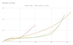
Here is a comparative plot with all of the tubes I have used in this circuit. Unfortunately I only took one data point with the 6384 at 1W with this final circuit, but I included it here for comparison.
I'll update with a 211 column when I get my hands on one to test with.
I'll update with a 211 column when I get my hands on one to test with.
Attachments
Here is a comparative plot with all of the tubes I have used in this circuit. Unfortunately I only took one data point with the 6384 at 1W with this final circuit, but I included it here for comparison.
I'll update with a 211 column when I get my hands on one to test with.
Great results, will the final build be able to support all of these different tubes given the unique pin configurations? Some sort of adapter system maybe?
I think I'll build two amplifiers. A smaller one for the 826 with the Edcor transformers, and then a larger one for the bigger tubes with the Electra-Print transformers. I'm envisioning something that takes an hour or so in the garage to switch/move connections around inside, so having a setup where I can mount sockets on a plate and then swap the plate. The 100W tubes have different filament votages and if I incorporate the ability to switch to a 211, I'd need to have a reconfigurable B+ as well.
I'm a little less optimistic that the 211 will be a stellar performer now that I have played with the VT-127A. I think it will be very low distortion in absolute terms, but will have that really low level high-order stuff from the Vg=0 crossing starting at less than 1W.
Listening to the VT-127A, though, I don't hear anything bad. That stuff is way down there close to the noise floor. I don't think I could tell the difference between that and the other tubes in a blind test. However, it still disappoints me.
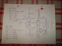
It's the same as what is shown in post #2 but I have increased the rails to +150V/-100V to accommodate the additional required swing for the lower mu tube.
The mosfet is a C2M1000170D.
Have you tried increasing the standing current by about 10X?
How about trying a high Gm triode in that position with a choke load?
I think I'll build two amplifiers. A smaller one for the 826 with the Edcor transformers, and then a larger one for the bigger tubes with the Electra-Print transformers. I'm envisioning something that takes an hour or so in the garage to switch/move connections around inside, so having a setup where I can mount sockets on a plate and then swap the plate. The 100W tubes have different filament votages and if I incorporate the ability to switch to a 211, I'd need to have a reconfigurable B+ as well.
I'm a little less optimistic that the 211 will be a stellar performer now that I have played with the VT-127A. I think it will be very low distortion in absolute terms, but will have that really low level high-order stuff from the Vg=0 crossing starting at less than 1W.
Listening to the VT-127A, though, I don't hear anything bad. That stuff is way down there close to the noise floor. I don't think I could tell the difference between that and the other tubes in a blind test. However, it still disappoints me.
Wow, two amplifiers, that's fun, having a plate to swap would definitely be convenient, I don't think I've seen a design that can run all of these different transmitters. Regarding the high order harmonics, if it sounds good it sounds good! Could always leave the VT-127A out of the rotation if it becomes bothersome.
I recently picked up some Electra-Print transformers for a 45 design, I really like them, haven't tried Edcors yet but you can't beat the price. I just bought a lot of 35 HY69 transmitting pentodes, not sure what I'm going to do with them yet, but they have excellent linearity as triodes and can swing into A2.
Have you tried increasing the standing current by about 10X?
How about trying a high Gm triode in that position with a choke load?
I could easily take it up to 3X or so with the board/heatsink it is on. I could also give it a CCS load and see what effect it has. My gut says it would make it better, I just don't know how much.
This will probably be my next line of inquiry.
Wow, two amplifiers, that's fun, having a plate to swap would definitely be convenient, I don't think I've seen a design that can run all of these different transmitters. Regarding the high order harmonics, if it sounds good it sounds good! Could always leave the VT-127A out of the rotation if it becomes bothersome.
I recently picked up some Electra-Print transformers for a 45 design, I really like them, haven't tried Edcors yet but you can't beat the price. I just bought a lot of 35 HY69 transmitting pentodes, not sure what I'm going to do with them yet, but they have excellent linearity as triodes and can swing into A2.
Luckily all of the 100T variants are pretty similar so the same operating point works for them. The grid bias varies with the different variants but the bias servo handles that. Unfortunately the 211 needs negative bias, which the bias servo wasn't made to handle.
My vote would be Pentode-connected HY69->211.
The HY-69 could be run as a driver tube pentode for something larger.
Luckily all of the 100T variants are pretty similar so the same operating point works for them. The grid bias varies with the different variants but the bias servo handles that. Unfortunately the 211 needs negative bias, which the bias servo wasn't made to handle.
My vote would be Pentode-connected HY69->211.
Thanks, I'll give that idea some thought, they are flexible tubes. In triode, remind me of a type 50, but with nearly double the gain and can run in A2.
Anyway, will follow along with your build, looking forward to more results.
- Home
- Amplifiers
- Tubes / Valves
- Corona: An Ultra-Low Distortion A2 DHT SE Amp Prototype