Hi, EVA,
I wanted to ask you about SMD components. I don't know much about these components, but for me building amps (including classD) using SMD components seems to always have a certain sound signature. I haven't tried the boutique SMD components like LC uses, though. I only tried ordinary SMD ones.
For example, I built UCD type amp using SMD components and ordinary components (1/8watt resistors). It seems I always prefer the ordinary component version. Why is this?
It makes me wonder about the "rule" that making classD, the best approach is to use SMD components. I found out that a bit longer PCB tracks (needed for ordinary components) gives neglectible effect, compared to wrong selection of mosfets (slow diode, huge charge properties, like you mentioned in the other thread), for example. For making classD, there are many more important factors than to the "rule" to use SMD, I think.
Workhorse said:Congratulations Evita..........your project really rocks!!!!
BTW:How about posting some waveforms??")
I can use the 100Ms/s storage mode of my oscilloscope to transfer waveforms to the computer and post them as I did in my SMPS projects, but most of the stuff above 20Mhz is lost this way, so you are going to see essentially pure square waves (that aren't actually so clean). I'll try to borrow a digital camera to take pictures directly from the CRT of the scope in analog mode.
For the moment I have tamed almost completely the PSU resonance with the help of more series-parallel 100n 50V 1206 SMD capacitors. Now there is a harmless 5.5Mhz resonance as a result of the leakage inductance of the electrolyitcs (I calculate <4nH each
 ) and the 200nF of SMD ceramic caps paralleled --> 5.6Mhz=1/(2*3.1415*sqr(200e-9*8e-9))
 There is 100Mhz ringing at the gates after each hard switching event, but it is not PSU resonance, it comes from the self-resonance of the own two TO-220 packages in series
The math matches quite well with datasheet parameters: 7.5nH (source) + 4.5nH (drain) = 12nH series in each TO-220, and 100pF Cd-s in the one turned off make a 110Mhz resonator --> 110Mhz=1/(2*3.1415*sqr(100e-12*24e-9))It seems that I have reached the switching "performance limit" of TO-220 packages so I'm probably going to need lossy RC snubbers to damp the remaining 100Mhz stuff.
lumanauw said:Hi, EVA,
I wanted to ask you about SMD components. I don't know much about these components, but for me building amps (including classD) using SMD components seems to always have a certain sound signature. I haven't tried the boutique SMD components like LC uses, though. I only tried ordinary SMD ones.
For example, I built UCD type amp using SMD components and ordinary components (1/8watt resistors). It seems I always prefer the ordinary component version. Why is this?
It makes me wonder about the "rule" that making classD, the best approach is to use SMD components. I found out that a bit longer PCB tracks (needed for ordinary components) gives neglectible effect, compared to wrong selection of mosfets (slow diode, huge charge properties, like you mentioned in the other thread), for example. For making classD, there are many more important factors than to the "rule" to use SMD, I think.
Properly laid out SMD with a continuous ground plane in the opposite PCB side achieves much better EMI inmunity than classic thru-hole parts. In this prototype, if I short the input pins, I can happily touch the drain tab of the lower class-D MOSFET with my finger and become myself a big FM antenna with little or no visible shifting in the idle self oscillating frequency. In comparison, the other high-power self-oscillating amp made with thru-hole parts exhibited much worse inmunity to its own EMI.
Remember that SMD chip capacitors are ceramic and that there are some types (high values intended for compact supply decoupling) that are very non linear, while others are very stable (usually low values). There are several dielectrics to choose (NP0, C0G, X5R, X7R, Y5V).
BTW: Sonics is a purely subjective topic.
BTW2: I got most of my SMD stuff in ebay for quite cheap, so I don't expect it to be particularly good quality. For example, I matched manually the +/-10% ceracmic capacitors used at the differential input to the modulator.
I tamed the remaining 100Mhz ringing by adding 10ohm and 100pF snubbers between drain and source of each switching MOSFET. Dissipation in the snubbers is very small, not enough to produce substantian heat in a 0.25W resistor.
According to the gate drive spike seen during opposite diode reverse recovery, I estimate reverse recovery di/dt to be 500A/us or so. This gate drive spike is actually produced across the source lead inductance terminal (7.5nH for TO-220), there is *no* real spike in Vgs, and the height of the spike with respect to gate plateau voltage tells you turn-on di/dt.
I measured output offset to be 26mV.
Idle current draw with 14V supply is only 0.3A with one channel working.
I was unable to measure or hear any beating frequencies produced by the 75Khz PSU, but the self-osc frequency is 330Khz. I'm considering reducing it to near 300Khz to see if I can find any beating phenomena.
12V push pull power supply transformer ringing
Shame on me...
Lazyness led me to *not* spread the two auxiliary windings (9 turns for +/-15V and 11 turns +18V) around the entire PSU toroid... Then, today I was wondering where was so much 13Mhz and 20Mhz radiated EMI coming from, even after adding RC snubbers to the primary windings to prevent them from resonating with push-pull MOSFET capacitance... Until I discovered that these two damn windings were acting as solenoids and antennas and its very high leakage inductance was resonating with the capacitance of the schottky diodes (MBR1100) and the resulting ringing (13Mhz and 20Mhz) was being happily radiated... (particularly through wiring as common-mode EMI between primary and secondary side grounds because I haven't RF coupled them yet).
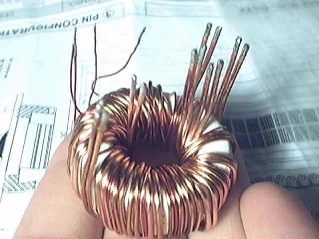
So I had to unsolder the PSU transformer from the PCB and redo the auxiliary windings spreading them evenly around the core. I took some pictures....
This picture shows the previous state of the transformer. Auxiliary winding turns were concentrated on a very small section of the toroid...
Re-done transformer with spread windings:
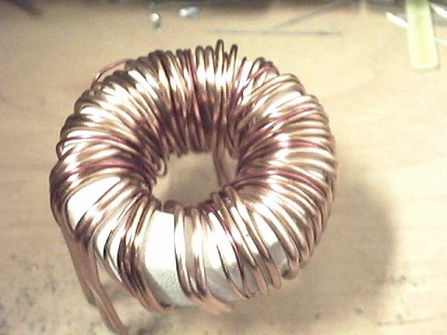
The lesson to learn here is that transformer leakage inductance is evil because all the voltage drop across this inductance is likely to be translated into radiated EMI...
Let's see how the new transformer works...
Off-topic:
Tekko, I have been watching most of the videos and pictures that you have online in your server. You won't get better results in electronics until you improve your methods and gain more understanding about circuit parasitistics. Long wires and bad PCB layouts are evil, their inductance stores energy and this energy always ends up being either radiated as EMI (that disturbs the own cuircuit and anything around) or dissipated as heat in the transistors. Also, your switching PCB layouts contain obvious parasitistics that could be easily avoided drawing them in a better way. Not to mention that you need a decent workbench to rest your prototypes on... Your wired point-to-point power-switching circuits remind me a lot of my first SMPS attempts 10 years ago (I blew a lot of IRFP460 back then).
Shame on me...
Lazyness led me to *not* spread the two auxiliary windings (9 turns for +/-15V and 11 turns +18V) around the entire PSU toroid... Then, today I was wondering where was so much 13Mhz and 20Mhz radiated EMI coming from, even after adding RC snubbers to the primary windings to prevent them from resonating with push-pull MOSFET capacitance... Until I discovered that these two damn windings were acting as solenoids and antennas and its very high leakage inductance was resonating with the capacitance of the schottky diodes (MBR1100) and the resulting ringing (13Mhz and 20Mhz) was being happily radiated... (particularly through wiring as common-mode EMI between primary and secondary side grounds because I haven't RF coupled them yet).
So I had to unsolder the PSU transformer from the PCB and redo the auxiliary windings spreading them evenly around the core. I took some pictures....
This picture shows the previous state of the transformer. Auxiliary winding turns were concentrated on a very small section of the toroid...
Re-done transformer with spread windings:
The lesson to learn here is that transformer leakage inductance is evil because all the voltage drop across this inductance is likely to be translated into radiated EMI...
Let's see how the new transformer works...
Off-topic:
Tekko, I have been watching most of the videos and pictures that you have online in your server. You won't get better results in electronics until you improve your methods and gain more understanding about circuit parasitistics. Long wires and bad PCB layouts are evil, their inductance stores energy and this energy always ends up being either radiated as EMI (that disturbs the own cuircuit and anything around) or dissipated as heat in the transistors. Also, your switching PCB layouts contain obvious parasitistics that could be easily avoided drawing them in a better way. Not to mention that you need a decent workbench to rest your prototypes on... Your wired point-to-point power-switching circuits remind me a lot of my first SMPS attempts 10 years ago (I blew a lot of IRFP460 back then).
The push-pull is much quieter now but it's still producing far more EMI than a single class D channel. This is quite puzzling, but even the optimum transformer seems to be a very efficient antenna.
I dropped the12V push-pull PSU clock to 128Khz for 64Khz switching (was 75Khz previously) and I obtained a more resonant-like behaviour this way, which gets rid of turn-on EMI. Five times 64Khz is 320Khz, and the class-D channel is oscillating at 330Khz, but I can't hear any 10Khz tone or anything (not even idle noise on the tweeter) when I turn the volume of the source to 0.
I dropped the12V push-pull PSU clock to 128Khz for 64Khz switching (was 75Khz previously) and I obtained a more resonant-like behaviour this way, which gets rid of turn-on EMI. Five times 64Khz is 320Khz, and the class-D channel is oscillating at 330Khz, but I can't hear any 10Khz tone or anything (not even idle noise on the tweeter) when I turn the volume of the source to 0.
Wow!
I dropped 12V push-pull operating frequency to 54.2Khz (108.4Khz clock) in order to achieve fully resonant operation. 55Khz is exactly 6 times 330Khz (self oscillating freq) but no crosstalk was appreciated. I had to touch the push-pull transformer with one hand and the open-circuit input jack with the other hand in order to be able to hear a cross-talk tone
I have only one channel working, though, so I still don't know if they are going to mutually bother themselves.
This is off-topic here, and if you use the search engine you are likely to find a few explanations of how to do it. If you are really interested, I could open a thread and describe my method in detalil when I have some time, but I find it quite obvious. In short, I use inkjet transparencies, positive presensitized PCB, traditional UV exposure, caustic soda developping and HCl + H2O2 etching (outdoors!!). Then I drill the boards, I cut the borders and I finish them with stone grinder.
I dropped 12V push-pull operating frequency to 54.2Khz (108.4Khz clock) in order to achieve fully resonant operation. 55Khz is exactly 6 times 330Khz (self oscillating freq) but no crosstalk was appreciated. I had to touch the push-pull transformer with one hand and the open-circuit input jack with the other hand in order to be able to hear a cross-talk tone
I have only one channel working, though, so I still don't know if they are going to mutually bother themselves.
Ipanema said:Hi Eva,
May I know how do you create those nice double sided PCB? Which method do you use?
Thanks.
This is off-topic here, and if you use the search engine you are likely to find a few explanations of how to do it. If you are really interested, I could open a thread and describe my method in detalil when I have some time, but I find it quite obvious. In short, I use inkjet transparencies, positive presensitized PCB, traditional UV exposure, caustic soda developping and HCl + H2O2 etching (outdoors!!). Then I drill the boards, I cut the borders and I finish them with stone grinder.
Crosstalk in self oscillating amplifiers
I assembled the second channel and put it to work too.
The crosstalk behaviour that I have observed is quite interesting:
- With no input signal both channels stay synchronized and there is no noise at all. I matched the critical resistors and capacitors so this is more or less an expected behaviour.
- If I fed the same signal to both channels, they keep synchronized almost all the time too.
- If I fed music to one channel and leave the input to the other channel shorted (with a speaker connected to the output) I can hear increasing crosstalk in the form of weak noise in the idle channel modulated by the music of the other channel, but this only happens up to a certain volume level (low), then crostalk disappears *completely* as I continue increasing volume. There seems to be a "noisy" transition from parasitistics-synchronized to free-running operation. This suggests that the best way to operate two self-oscillating modulators placed together is to to use two different frequencies (different frequency compensation).
Ah...my god. You are officially insane. And I like it.
I was going to write you regarding the design of offline SMPS for some amplifier designs I am licensing...but now you've got me interested in this thing. Please let me know what your terms are if you plan to license this circuit design. I am interested.
I was going to write you regarding the design of offline SMPS for some amplifier designs I am licensing...but now you've got me interested in this thing. Please let me know what your terms are if you plan to license this circuit design. I am interested.
Uhm... I have reduced the noise crosstalk by 6dB or so by changing the suppy decoupling strategy and removing a bit more of 10Mhz-and-above RF from the rails... There is still some room for improvement, I'm starting to love SMD chip ceramic caps...
I also found that a pair of parallel 1uF 100V electrolytics are extremely good at ironing the resonance peak that results when you parallel big electrolytics with 100nF chip ceramics. The resonance in the 5Mhz to 7Mhz zone (depending on how much ceramics I put) is now completely gone.
BTW: Now the EMI radiated by the prototype is almost completely ringing free, only clean switching transients are radiated.
I'm insane and you like it? Thanks Messages like yours are a good source of motivation. Of course I'm always open to business I'll try to mail you, otherwise mail me or contact me through messenger (see my forum profile),
Oh, but I only deal with the best body diodes What do you think? Mine only store 41nC (typ.) for 22A and 100A/us so they are piece of cake to recover. The awful body diodes are the ones that store 10 or even 100 times more charge  You'd rather keep those away from any class D amplifier (throw them in the nearest push-pull SMPS...)
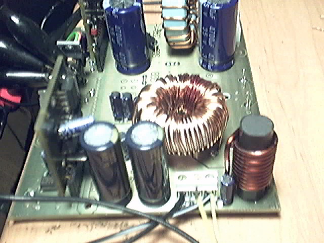
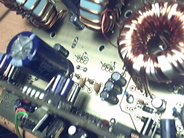
Stereo pictures:
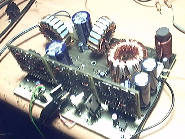
Note the added small electrolytics and 100n SMD ceramics (there are more on the bottom side...)
I also found that a pair of parallel 1uF 100V electrolytics are extremely good at ironing the resonance peak that results when you parallel big electrolytics with 100nF chip ceramics. The resonance in the 5Mhz to 7Mhz zone (depending on how much ceramics I put) is now completely gone.
BTW: Now the EMI radiated by the prototype is almost completely ringing free, only clean switching transients are radiated.
EnvisionAudio said:Ah...my god. You are officially insane. And I like it.
I was going to write you regarding the design of offline SMPS for some amplifier designs I am licensing...but now you've got me interested in this thing. Please let me know what your terms are if you plan to license this circuit design. I am interested.
I'm insane and you like it? Thanks
Messages like yours are a good source of motivation. Of course I'm always open to business I'll try to mail you, otherwise mail me or contact me through messenger (see my forum profile),Workhorse said:Hey Evita,
What about "Reverse Body Diode Conduction" issue in this project.......
Oh, but I only deal with the best body diodes
What do you think? Mine only store 41nC (typ.) for 22A and 100A/us so they are piece of cake to recover. The awful body diodes are the ones that store 10 or even 100 times more charge You'd rather keep those away from any class D amplifier (throw them in the nearest push-pull SMPS...)Stereo pictures:
Note the added small electrolytics and 100n SMD ceramics (there are more on the bottom side...)
Eva said:Oh, but I only deal with the best body diodes
Evita, then you must be using some "Specific Mosfets" with low Qrr & Trr..........to get rid of body diode issues....
Could you suggest some part numbers?

sawreyrw said:Eve,
I agree with others who say your stuff is impressive, but show us a schematic of what you are really doing. Then I will really be impressed.
Rick
Sorry, I'm not going to show my schematics, board layours are more interesting. You can find a lot of schematics already published and mine are not that different. If you are working on your own class D projects, you should already have your own schematics and layouts and you can easily learn tips from my pictures and explanations. If you are not deeply involved in class D, then you have still a lot to learn and I don't want you to just copy me.
- Status
- This old topic is closed. If you want to reopen this topic, contact a moderator using the "Report Post" button.
- Home
- Amplifiers
- Class D
- Cool and small 2x150W class D full-range car amplifier