Evita,
Do you know that IRF has fully integrated solution for class-D upto 500W@4Ohms....their new chip
http://www.irf.com/product-info/datasheets/data/irs2092.pdf
reference design
http://www.irf.com/technical-info/refdesigns/iraudamp5.pdf
Do you know that IRF has fully integrated solution for class-D upto 500W@4Ohms....their new chip
http://www.irf.com/product-info/datasheets/data/irs2092.pdf
reference design
http://www.irf.com/technical-info/refdesigns/iraudamp5.pdf
Eva said:Input voltage to the PSU will usually sag during bass transients, and you usually lose 2V in the gate driver. There are also voltage drops across the PCB ground tracks and across the own source leg and bonding wires of the MOSFETs. Sometimes you may end up with less than 8V internally at the gates during maximum current consumption periods if you don't do anything about that. Switching times depend on Vgs too, and I prefer to have things more under control.
Having a high voltage at the gates is more advantageous for some MOSFETs than for others, but you may easily achieve 30% lower Rds-on when you need it.
thanks for the info. I'll experiment and implement it on the new SMPS and post what happens.

Workhorse said:Evita,
Do you know that IRF has fully integrated solution for class-D upto 500W@4Ohms....their new chip
http://www.irf.com/product-info/datasheets/data/irs2092.pdf
reference design
http://www.irf.com/technical-info/refdesigns/iraudamp5.pdf
Nah, this is too easy and I don't like IRS2092 because comparator reference and op-amp IN+ are not externally accessible, and analog section is limited to +/-5V supplies. On the other hand, I happen to have a few IRS20954 that a nice guy sent to me, and they fit this project except by the fact that they have the same weak 1A gate driver as IRS2092. The 3A drivers in IR2010 are more suitable for handling the 42nC gate charge of IRF540Z at 300Khz.
lumanauw said:I've experimented with selfoscilating UCD style with LM311 comparator. The DC offset is pretty bad (>200mV). Why is this? Is this because I use pull-up resistor (2k) from pin 7 to pin 8?
Try a balanced (impedance) approach at the input. The output pull-up should not cause any offset. I haven't had any trouble with this.
Tekko said:Very nice

Btw do you happen to know why i cannot get a level shifter to work with BC557 or similar xsistors ?
Post your level shifter schematics and describe the problem in one of your threads. Then give me a link and I will take a look.
Eva said:Nah, this is too easy.
OOPS!! I forget to remember that Evita like challenges more than anything else.......
Hi, Eva
Wouldn't be this one more easy? It is for my car and 6 channel UCD based amplifier(135*120mm). Symmetrical 35V supply line could give at least 100W into 4 ohm and surely and it is very efficient.really cool. Amplifier self osc frequency is 370KHz but I sync. all of them to 424KHz. Any way I like this UCD. Thanks to Bruno Putzey.
And sorry if this is off topic!
Regards
Attachments
mhtplsh said:Whortless,
U made this?
Give details about it.
From where u bought UCD chip?
Yes sure. I will make some measurements on it then will post the details. I did not bought an UCD chip. It uses discrete semiconductors. U can find details searching on diyaudio " UCD" , philips app. notes UM10155 etc. There is some difference on my circuit but, the main idea and the circuit is similar.
Regards
Attachments
Whortless said:Hi, Eva
Wouldn't be this one more easy? It is for my car and 6 channel UCD based amplifier(135*120mm). Symmetrical 35V supply line could give at least 100W into 4 ohm and surely and it is very efficient.really cool. Amplifier self osc frequency is 370KHz but I sync. all of them to 424KHz. Any way I like this UCD. Thanks to Bruno Putzey.
And sorry if this is off topic!
Regards
Whortless said:
Yes sure. I will make some measurements on it then will post the details. I did not bought an UCD chip. It uses discrete semiconductors. U can find details searching on diyaudio " UCD" , philips app. notes UM10155 etc. There is some difference on my circuit but, the main idea and the circuit is similar.
Regards
Dear Eva,
Please excuse me for these posts. I wouldn't like to interfere in to your thread. Just would like to imply "there are some easy ways of creating Class-D amps". But, the resulting posts made me sorry and exceeded the aim of my post.
For DIYer's ; U can ask your questions direcly by e-mailing to me and please wait for measurements (scop, signal results, THD etc.). I will open a new thread on my 6 CH UCD.
Regards
No problem, but you should open your own thread and post more information because I'm sure that there is going to be a lot of car-audio people interested, particularly once they become aware of the advantages of class D
BTW: What output MOSFETs are you using? I became a bit puzzled when I saw TO-247 devices because they usually have large dies and large gate charges, and I think that the UcD-style discrete gate driver only performs well with ultra-low gate charge MOSFETs like the infamous STP14NF12FP featuring 16nC typ.
BTW: What output MOSFETs are you using? I became a bit puzzled when I saw TO-247 devices because they usually have large dies and large gate charges, and I think that the UcD-style discrete gate driver only performs well with ultra-low gate charge MOSFETs like the infamous STP14NF12FP featuring 16nC typ.
Eva said:No problem, but you should open your own thread and post more information because I'm sure that there is going to be a lot of car-audio people interested, particularly once they become aware of the advantages of class D
BTW: What output MOSFETs are you using? I became a bit puzzled when I saw TO-247 devices because they usually have large dies and large gate charges, and I think that the UcD-style discrete gate driver only performs well with ultra-low gate charge MOSFETs like the infamous STP14NF12FP featuring 16nC typ.
In fact I like the TO-247 devices because of their large die size. I did not measured gate signals yet but, when I measured with DC voltmeter H&L side mosfet levels are same and Vdrv/2 means 4-5V. Also I am measuring the frequency of self osc from L gate( same with H gate). However frequency meter shows 3 times higher frequency on output from the G-S measurements. The reason may be ringing on output and could be corrected with playing snubber values. The output mosfets IRFP250N or IRFP150N both worked well(~110 to 150nC gate charge
) and also sound quality is more good then my HIP4081 project.Will open a new thread soon interested DIYer's should wait.
Kind regards
PS: There are many good high current transistors from ZETEX in a SOT23 package up to 5-7A peak( but now I am using BC807 and waiting for philips 5240T device for quick shut, this one could improve quality a bit! ).
You should consider your MOSFET choice again. These devices (IRFP150N/IRFP250N) are about the worst stuff you can choose for class D. Body diodes are ultra-slow, capacitances are high, gate charge is enormous. You are probably going to see a big waveform disaster if you crank the volume up to enter CCM (continuous conduction mode) while looking at the gates and drains with a 100Mhz (or better) oscilloscope. On the other hand, parts with Z suffix from IR usually have excellent body diodes.
BTW: In average you are always going to measure almost 1/2 gate supply voltage between gate and source. This is not a good indicator of gate charging and discharging speed.
BTW: In average you are always going to measure almost 1/2 gate supply voltage between gate and source. This is not a good indicator of gate charging and discharging speed.
Eva said:You should consider your MOSFET choice again. These devices (IRFP150N/IRFP250N) are about the worst stuff you can choose for class D. Body diodes are ultra-slow, capacitances are high, gate charge is enormous. You are probably going to see a big waveform disaster if you crank the volume up to enter CCM (continuous conduction mode) while looking at the gates and drains with a 100Mhz (or better) oscilloscope. On the other hand, parts with Z suffix from IR usually have excellent body diodes.
BTW: In average you are always going to measure almost 1/2 gate supply voltage between gate and source. This is not a good indicator of gate charging and discharging speed.
Ok many thanks. My first prototype was stereo for this circuit(somewhere in here under the topic "Discrete input modulator"). I give it to my friends. They tried it with STW50NB20 which is an suggested mosfet by Tripath for TA3020 and get similar results. Anyway I am now speaking on the basic measurements and listening. I put antiparallel fast diodes to DS legs of each mosfet. But, speaking on this circuit is not logical without measurement.
Also my main question was this. My stereo version could be build with 18N100 or 14N100 as you implied recently and output power could reach to 200W RMS per CH as philips/Bruno Putzey said. Why you did not prefer Philips UCD ? It was more easy from yours. If there is a real preference reason let us to know. We are always like your desings and would like to learn a bit much.
Regards
I like to do things my own way
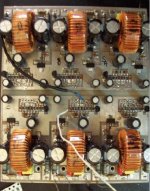
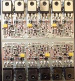
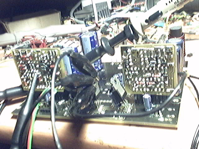
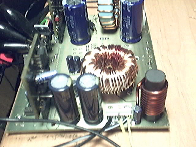
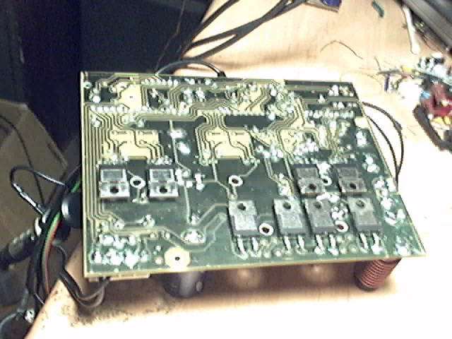
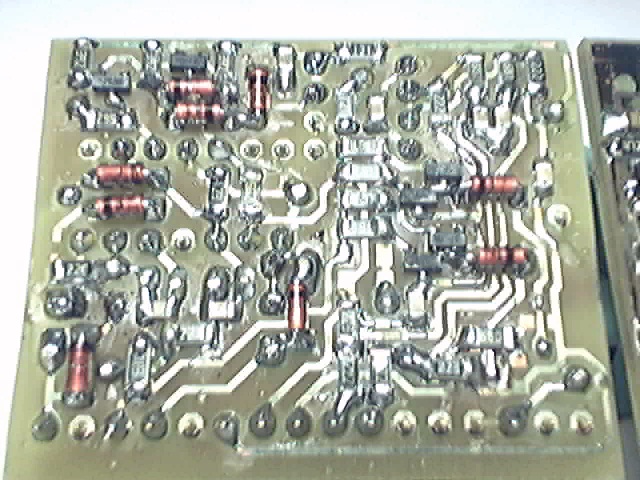
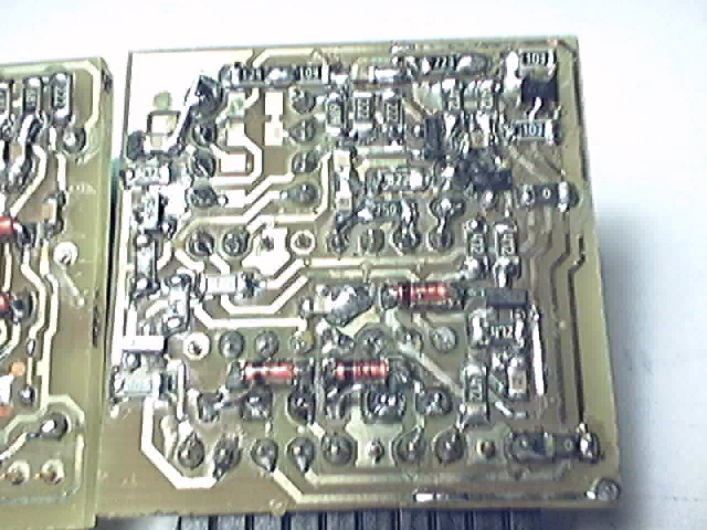
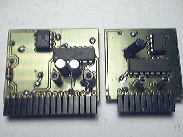
Today I finished assembling the push-pull PSU and one channel and it worked at the second attempt (I swapped a 7815 by a 7915 in the first attempt).
PSU transformer is made from a 33mm 3E25 toroid core with 13+13:5+5 turns ratio (2.6) for the main windings, and 9 and 11 turns for the +/-15V (op-amps) and +18V (gate drive) auxiliary windings respectively. SG3525A clock is 150Khz, which leaves a gentle margin before saturation. Supply rails are approx. +/-36V with 14.4V input. They are expected to sag to +/-28V under load with 12V input. The push-pull runs perfectly balanced and in a resonant fashion with almost zero voltage turn on.
A dead short on the secondary side (caused by a pair of blown IRF540Z) with 500ns duty cycle in the primary side causes the push-pull to pass 60A peak. The turn-off drain spikes of both MOSFETs climb to 60V and 70V respectively for 60A, and this is without any snubber and with the auxiliary supply for primary gate drive disabled, so leakage inductance of the transformer is quite good. Leakage inductance tends to resonate with 14V drain-source capacitance at 16Mhz so it seems to be in the 500nH range.
Concerning the class D section:
Output inductors are wound on 33mm OD MPP cores to achieve 27uH at 1A falling to 20uH at 20A, which is the current limit. Idle self-oscillation frequency is 330Khz.
With 14.4V supply, the prototype plays full music output into a 8 ohm 3-way speaker without *any* heatsink and with the power devices still feeling cool to the touch.
Switching crossover times (0-70V) are in the 20ns range. Gates are fully charged to 18V within 150ns of the beginning of turn on, and fully discharged to 0V within 20ns of the beginning of turn-off. Dead time is in the 45ns range in one way and 20ns in the other way (shame on IR2010).
Main power supply resonance as seen from the class D section is 52Mhz and it becomes excited by body diode reverse recovery cross-conduction spikes as usual. It was splitted into two substantially smaller ones, 7Mhz and 100Mhz, by adding four 100nF 50V 1206 SMD capacitors in series-parallel (100V parts are on the way). Math tells that the series leakage inductance of both 4700uF 35V electrolytics is in the 6nH range, so adding parallel bypass film caps here is COMPLETELY USELESS because they are in this inductance range too.
This definitely calls for a distributed bank of a dozen parallel 100nF 100V 1206 capacitors between +V and -V in order to get negligible RF ripple in the supply rails without giving up on fast switching. 1210 capacitors are even better but too expensive for me.
BTW: The specs of my oscilloscope state that it's -3dB down at 40Mhz
Edit: Some pictures...
Eva said:I like to do things my own way
And you do a damn fine job. Beautiful project and impressive numbers. Thank you for sharing.
A tip for probing around your circuits that was in some old app notes (and more recently a seminar by a TI fellow)...
Sacrifice a click pen for the spring inside. Use some needle nose pliers to fashion one end of the spring into a straight lead that will act as a nice ground probe. Remove the clip attachment tip on the probe and wrap the spring around the grounded body of the scope probe. Now you have a nice, cheap low inductance ground lead to get the most out of your probe and scope.
- Status
- This old topic is closed. If you want to reopen this topic, contact a moderator using the "Report Post" button.
- Home
- Amplifiers
- Class D
- Cool and small 2x150W class D full-range car amplifier