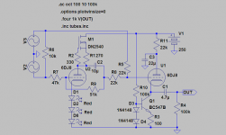
Would anything good happen for PSRR if one DC couples
the plate of U2 to the source node of M1? At the top end
of R1? Instead of powering U2 directly from B+ (with the
usual power ripples unrelated to the music signal...)
Don't think it would greatly affect constant currentness seen
by U1? But I'm not entirely free to play with tubesims right
now to confirm that theory. My lunch break is about over...
I got four trays 20 deep to test, and boards are stacked
double wide, so I guess thats like 160. I won't be in much
mood to play with anything electronic by the time I get
home.
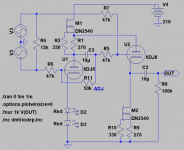
R, I understand... But C for what? Its OK U2's plate ripples,
as long as its in unity with the input signal(s)... I think its
called an augmented follower or something...
I realize its sort of cheating to augment the plate off only one
side of the source, but what the hey... Its better than power
supply noise... The cathode still follows the blended average.
as long as its in unity with the input signal(s)... I think its
called an augmented follower or something...
I realize its sort of cheating to augment the plate off only one
side of the source, but what the hey... Its better than power
supply noise... The cathode still follows the blended average.
revintage said:Why not try it with 6DJ8/E88CC?
that would be nice - still i have a problem to find those DN fet's.... i thought to go with c4s as ccs but with this last schematic i think i can't do it with c4s ccs............
revintage said:The problem, as I see it, is that frequency response is not so good through the PF.
??? You lost me completely.
I knew what you ment!
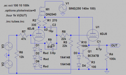
With your solution and 100mV/100Hz ripple at the PSU you get ca 40uVrms at the output. With my conventional solution you get ca 35uVrms. Without anything at all, ripple is 3mVrms.
So yours win as you save two components.
This is the circuit with ripple at the PSU:
With your solution and 100mV/100Hz ripple at the PSU you get ca 40uVrms at the output. With my conventional solution you get ca 35uVrms. Without anything at all, ripple is 3mVrms.
So yours win as you save two components.
This is the circuit with ripple at the PSU:
Attachments
revintage....
you are good with Spice...
can you PLEASE (!) simulate the circuit that has the same ccs that you have used in your last schematic in the second stage, also in the first stage - so that i can use two exactly the same ccs's ... the ones i can build - DNxxxx i can't find in Delta Quadrant....
and please tell me how it will behave... is it good or better to go with the first few sch's.....
This seems like a lot of discussion over the output of a differential amplifier.
If the diff amp can drive the load, you can just take the output of the side that has the phase you want (why get into increased distortion and complexity?). Its only if you have an adverse load condition (10K input on a transistor amp for example) that you might want to use some sort of balun circuit.
If the diff amp can drive the load, you can just take the output of the side that has the phase you want (why get into increased distortion and complexity?). Its only if you have an adverse load condition (10K input on a transistor amp for example) that you might want to use some sort of balun circuit.
Enhancement mode device with a floating bias battery is an
option too. Check out the specs on some of the new IGBTs.
IXGH6N170A will flip your lid! Nothing that fancy is required.
12V keyfob battery for car alarm is a convenient package...
May be cheaper and easier to pair with some commonplace
enhancement gated FET than shop in vain for high voltage
depletion mode sand (in some quadrants).
If you went Pentode, 6DJ8 is made to tolerate an elevated
filament. Maybe they can all still light off the same supply?
revintage said:I knew what you ment!
With your solution and 100mV/100Hz ripple at the PSU you get ca 40uVrms at the output. With my conventional solution you get ca 35uVrms. Without anything at all, ripple is 3mVrms.
So yours win as you save two components.
This is the circuit with ripple at the PSU:
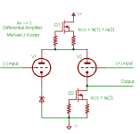
I thought eventually it would start looking like the ones in this
thread:
http://www.diyaudio.com/forums/showthread.php?postid=1546303#post1546303
But what's the problem with a diffamp again? You don't want
any gain at all?
Michael
Attachments
@Michael Koster - it is nothing wrong with the differential - i might still go with it.... it is looking nice - it is looking simetric, clean....
regarding the gain - for sure i do not need gain bigger than 1.... if it is less it will not be a problem but again i would not like to go lower than half of the oputput voltage i allready have at the WM8740 output..... so at the end i am looking to have at least 1V rms at the output of the dac.... not less than that..... it would make me even more happy if i could go close to 2Vrms output from the dac .....
regarding the gain - for sure i do not need gain bigger than 1.... if it is less it will not be a problem but again i would not like to go lower than half of the oputput voltage i allready have at the WM8740 output..... so at the end i am looking to have at least 1V rms at the output of the dac.... not less than that..... it would make me even more happy if i could go close to 2Vrms output from the dac .....
Michael,
We already covered that one, as kenpeter already suggested it. The problem though is that it´s worthless due to severe THD!
But if you substitute the Zener with an unbypassed resistor things get a little better.
In the unrealistical event that you could have one CCS on top and one with half the current at each cathode this would be the winner ! It works wonderfully in Spice but I doubt it will work IRL......
I adjusted and simplified it to work well IRL in post 43 but then you loose 6dB. Given the high output from a CD/DAC this just makes it better
We already covered that one, as kenpeter already suggested it. The problem though is that it´s worthless due to severe THD!
But if you substitute the Zener with an unbypassed resistor things get a little better.
In the unrealistical event that you could have one CCS on top and one with half the current at each cathode this would be the winner
! It works wonderfully in Spice but I doubt it will work IRL......I adjusted and simplified it to work well IRL in post 43 but then you loose 6dB. Given the high output from a CD/DAC this just makes it better
- Status
- This old topic is closed. If you want to reopen this topic, contact a moderator using the "Report Post" button.
- Home
- Amplifiers
- Tubes / Valves
- converting BAL to UNBAL using tubes and without transformers