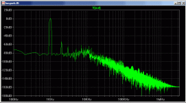
2VRMS nets you about 1VPP at the output, with real low impedance.
There's enough headroom at the input to drive that signal entirely
into either grid alone or together.... Plate swings no higher than
205V, even in the worst imbalance. Plenty of volts for the typical
CCS to function (assuming typical means 10M45S).
There's enough headroom at the input to drive that signal entirely
into either grid alone or together.... Plate swings no higher than
205V, even in the worst imbalance. Plenty of volts for the typical
CCS to function (assuming typical means 10M45S).
And I just discovered, if you bypass U1's cathode to ground
with a good cap (I simmed 47uF), the "missing half" of the
output signal then appears at U2's cathode. Netting 1.8VPP
I guess that means you could dumb down U1's cathode to
just a 180ohm and then bypass it, or perhaps some green
or blue LED alone would do about the same...
with a good cap (I simmed 47uF), the "missing half" of the
output signal then appears at U2's cathode. Netting 1.8VPP
I guess that means you could dumb down U1's cathode to
just a 180ohm and then bypass it, or perhaps some green
or blue LED alone would do about the same...
OMG.......
so many replies - guys - THANKS from the bottom of my heart......
i almost fell from the chair when i saw that many replies.....
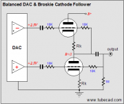
i was thinking of using WM8740 d/a converter - single chip - and to add balanced to unbalanced converter at the output of the chip....
so - yesterday i was Googling a bit and found those two schematic from Mr. Broskie..... they are cathode followers and i think they just might work..... i will attach those sch in this post - hopefully this will not violate copyright because it is stated that the sch's are from Mr. Broskie......
what do you think guys related those two schematics... could they match the quality of the WM8740 dac .....?????? i really do not need gain in this stage - only conversion and a little bit of a twist to add some tube flare in the sound...... nothing more......
so many replies - guys - THANKS from the bottom of my heart......
i almost fell from the chair when i saw that many replies.....
i was thinking of using WM8740 d/a converter - single chip - and to add balanced to unbalanced converter at the output of the chip....
so - yesterday i was Googling a bit and found those two schematic from Mr. Broskie..... they are cathode followers and i think they just might work..... i will attach those sch in this post - hopefully this will not violate copyright because it is stated that the sch's are from Mr. Broskie......
what do you think guys related those two schematics... could they match the quality of the WM8740 dac .....?????? i really do not need gain in this stage - only conversion and a little bit of a twist to add some tube flare in the sound...... nothing more......
Attachments
or should i go with the design that kenpeter posted..... btw. thanks for drawing it for me - it was needed (like A.Wright told it would be......)......
i would ceratinly need some advice - since the WM8740 is looking very nice (very good chip) to me and i would use the Opus dac from Mr. Russ White posted on this site in digital section...
i would ceratinly need some advice - since the WM8740 is looking very nice (very good chip) to me and i would use the Opus dac from Mr. Russ White posted on this site in digital section...
It is not acceptabe to add caps at the input!
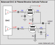
I adjusted kenpeters circuit, that suffered from severe THD, taking the DACs offset in account. I also change the tube to a better one.
Zout ca 1,5k. Well below 0,1% THD at max out from the DAC.
The filter between the cathodes had to be added to adjust a 2dB lift from 100kHz that I can not explain.
I adjusted kenpeters circuit, that suffered from severe THD, taking the DACs offset in account. I also change the tube to a better one.
Zout ca 1,5k. Well below 0,1% THD at max out from the DAC.
The filter between the cathodes had to be added to adjust a 2dB lift from 100kHz that I can not explain.
Attachments
revintage said:It is not acceptabe to add caps at the input!
I adjusted kenpeters circuit, that suffered from severe THD, taking the DACs offset in account. I also change the tube to a better one.
Zout ca 1,5k. Well below 0,1% THD at max out from the DAC.
The filter between the cathodes had to be added to adjust a 2dB lift from 100kHz that I can not explain.
so this has been simulated according to WM8740 dac ?????
is this correct - according to the offset of the WM8740??
what is the gain of this circuit??
Gain is just below -6dB. So you get in the ballpark of 1Vrms.
Who needs 2Vrms and for what? Even poweramps usually needs only 0dBU.
Personally I prefer the semipro std -10dBU.
And yes, I checked the WM8740 spec. before I designing this.
But I recommend using an amorphous Lundahl(ex. LL1690) if you want to listen to music........
Who needs 2Vrms and for what? Even poweramps usually needs only 0dBU.
Personally I prefer the semipro std -10dBU.
And yes, I checked the WM8740 spec. before I designing this.
But I recommend using an amorphous Lundahl(ex. LL1690) if you want to listen to music........
revintage said:Gain is just below -6dB. So you get in the ballpark of 1Vrms.
Who needs 2Vrms and for what? Even poweramps usually needs only 0dBU.
Personally I prefer the semipro std -10dBU.
And YES! I checked the WM8740 spec. before I designed this.
But I recommend using an amorphous Lundahl(ex. LL1690) if you want to listen to music........
thanks for the reply..... of course - if i could afford a transformer - i would use tha option for sure..... that would be probably the best option....really.....
i do not know - maybe i would do that way afterall.......maybe i will.....hmmmm......
sunrise said:it seems to me that Ludahl does not have LL1690 transformers......
i was wrong - i found it...... http://www.lundahl.se/pdfs/datash/1690.pdf
i have some double C cores to do the job.....but i think they might be a bit small..... have to check the crossection of the core and i will let you know..... 
it would be perfect if i could build it..... on that core.....
have you any suggestions abotu the dimensions of the coil and values needed regarding to WM8740.....??????
it would be perfect if i could build it..... on that core.....
have you any suggestions abotu the dimensions of the coil and values needed regarding to WM8740.....??????
revintage said:Think you missunderstod, I ment: Build the circuit not the tranny
oh boy..... i missunderstood all right
ahahahah ......o.k. - have to think about everything .....
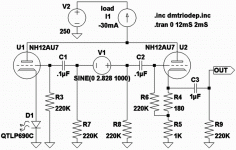
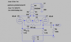
DN2540 alone maybe isn't the stiffest possible CCS,
but it'll do fine with a little power supply filtering.
I used 12AU7 rather than 6DJ8 for a reason. Because
2.828V Peak to Peak (2VRMS) would clip at the amp's
input and/or the CCS voltage limit (220V?) when the
input became unbalanced (grounded on either end).
Mu of 6DJ8 was too high, and ideal quiescent power
grid bias too close to the input signal level involved.
It has -6db loss because the other "half" shows up
below the other "unused" cathode. He hasn't yet
discovered that you can bypass that point to GND.
The missing -6db then re-appears at our intentional
output's cathode.
Havn't simmed Rev's mod yet, I'm not sure how his
driving signal works? What Spice is ".four"? I am too
new at LTSpice to know all command line tricks.
I see that getting rid of my "unacceptable" input cap
means adding an "acceptable" wholenother power
supply worth of extra parts, or perhaps a battery.
Battery lasts long for a fixed grid bias application,
its simple and quiet enough to be tempting.
----------------------------------------------------------------
Broskie's simplified circuit doesn't show the resistor
string to establish his grid biasing, nor his tricks to
get the PSRR to come out good. Broskie follower is
not as simple as drawn in that post. If low parts
count is going to be a consideration here at all?
You can't compare complexity without the supporting
components. Countless how many "simple" amps
(on paper) needed 15 different supply voltages....
revintage said:I adjusted kenpeters circuit, that suffered from severe THD, taking the DACs offset in account.
Its balanced, and DAC DC offset (from DAC GND?) isn't relevant
to this amp unless you also add a ground loop problem anyhow.
You are assuming it has a DC offset and no output caps? I am
not sure how common that is...
- Status
- This old topic is closed. If you want to reopen this topic, contact a moderator using the "Report Post" button.
- Home
- Amplifiers
- Tubes / Valves
- converting BAL to UNBAL using tubes and without transformers