Bear,1)It seems to me that IF you had the stock original cone, placed it's face on a flat smooth floor, put a flat smooth surface across the neck of the cone, that most so-called "heavy" woofer cones would support that much mass and more. Probably would work with the cone turned the other way too.
2)Fwiw, it seems like one could build an extremely strong cone assuming the driver was limited to frequencies below something like 50-60Hz, given that the cone mass could be higher than for the typical woofer, one that is expected to run up past 300Hz. Of course this isn't a mass market driver I'd expect. Seems plausible.
3)And Art, that's one heck of a STIFF suspension there! Is it all in the spider?? Single spider??
1) Been there, done that, got the T-shirt-the old school "heavy" woofer cones are no where near as strong as some of the new breed, but that is to be expected, they only had to deal with a fraction of the power current drivers can handle.
2) Powersoft is doing just that with the M-Force moving magnet drivers driven by I-PAL, which also has the advantage of better re-use of back EMF power, increasing efficiency, reducing heat in the amp/magnet system.
3) The B&C 18TBW100, SW115 and 152 (The second #s in B&C's drivers are voice coil diameter in MM) all use a double silicone spiders and triple roll surrounds, both of which become progressively "tighter" with increased excursion.
Unlike the Gauss loudspeakers from the 1970's, the first to use double spiders that I recall, B&C's double silicone spiders do not make their drivers "growl" like a bear.
The diaphragm to phase plug restriction in HF drivers has resulted in virtually no advances, other than lighter neodymium magnet structures and "survivable" diaphragms and voice coils, since the middle of last century.
During the early 1970's when I first became involved in Pro audio, LF driver's output has increased by an order of magnitude, while distortion has been reduced. At least some things are getting better!
One thing not getting much better is sound providers in large venues continued placement of vast arrays of sub-woofers on the ground, resulting in the first 1/3 of the audience area having "cartoon" bass twice (or more) as loud as is heard in the rest of the venue, with a sound "engineer" mixing in the sweet spot, never bothering to walk the venue because the system technician told him his array simulator had insured the system was "optimized" for the venue.
By simply flying the bass arrays, the inverse distance law could even out the bass response over the entire venue to within a few dB.
Using flown cardioid or end-fire arrays the uniformity of response could be improved even more by reducing the rear output of the sub arrays, which also considerably cleans up the stage sound, improving audio clarity by reducing the "wall of mud" coming from the rear radiation.
But we now go to "see" shows, can't have those pesky sub-woofers interfering with someone's view of video image of a face blown up to a size that makes a nose hair looks like a pool cue…
Art
Silicone? Must be silicone impregnating something woven, I would expect??
Must be a trick formulation of silicone too... one that likes a whole lot of bending!!
Not your homeowner's RTV in a tube!
Well they like the bass extension they get when the mouth looks 2x the size, I guess?
Whatever, it's been a long long time since I heard any sound in a big venue be worth a damn - it sure is LOUD though! Loud, loud, loud... thump, thump, thump... sizzle, sizzle, sizzle. Maybe they could shelve everything above about 7kHz down 6-10db so there might be some midrange?
Well I wear earplugs as a matter of course in almost all live shows anyhow, but even with the HF attenuation, there's still way way too much hash and sibilence flying around, imho.
For many old type theater sized venues, the sound tends to be rather carp since the engineer mixes for himself and the sides tend to have really awful modes with horrific suck outs and suck ins... at least the ones I've been at recently. Ah well, don't get me started...
Well, it's neat that they've gotten these drivers to perform so well... if I ever "go for it" and build up some sort of high output LF section of monster size, guess these are the "cat's meow"!
Wreckingball,"Also very interesting to note is that the combined Re of the drivers used in this sim, 5 drivers wired in parallel, is 1.06 ohms. Note that the strong and wide impedance peaks lift the system impedance up to 2x that (well over 2 ohms everywhere in the passband, This is another effect that only full sized horns have - the entire system impedance is higher than the resistance of the drivers used. This has some pretty major implications that I'm not going to discuss right now, but it's a huge benefit.")
Speaking of which, and while not derailing, is there a link to a paper for what you didn't want to go into below, that can describe this in more detail, or should I say expand on the implications?
JAG's insight was an eye-opener to me, as I have never before given much time to the study of "full size", or virtually "full size" horns, as they are a "pipe dream" in my world of transportable systems requiring the best possible sound output and quality for a given trailer volume. The volume to quality output ratio does not change whether filling multiple 54' trailers , or a single 5'x 8' trailer, as I have limited my system to presently.
1) A full size horn puts considerably less pressure on the driver than the small FLH or TH we use for portable use, which will translate to lower distortion for a given excursion.
2) A full size horn's higher impedance means more drivers can be used on any given amp channel. Each doubling of drivers reduces excursion demands, also reducing distortion.
The increased impedance (all typical "small" TH and FLH have an impedance minima equal to the driver's DCR) increases the damping factor control the amplifier provides for a given wire gauge.
3) A full size horn's huge mouth dimension increases forward gain, increasing sensitivity similar to the "barn door" boundary employed in old RCA and Altec theater horns.
A few sheets of weather and bug proof LP SmartSide panels can add 3dB forward gain and hardly reduce the volume to quality output ratio.
"Barn doors", regardless of the material the OP ultimately decides to go with, could reduce his capital expenditures and work by 50% for the same output level in front of the system, while reducing unwanted rear radiation.
Art
Thanks Art, that confirms some of what I thought, plus expanded on it.
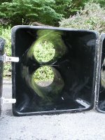
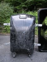
All this talk about huge horns reminds me of the first pro musician gig I had circa 1985, where we used to lug these around everywhere (plus the extension flares not in pic) see attachment. Not sure how effective they were vs other LF boxes of their day (EV 4050's etc), but you could break them down and stack them.
Enough of my babbling, carry on gents, this is very educational...
Attachments
Thinking of air pressure in terms of frequency-domain RMS equivalency is very counterintuitive to me. In my field of work (using a large heat source to turn propellers and to make electricity), I deal with four types of air pressure - gauge pressure, absolute pressure, stagnation pressure, and Mach pressure. . . . Frequency domain RMS pressure went right over my head!1. Hornresp calculates the peak pressure. For your comparison purposes you need to use rms pressure. The linear force of 165 pounds then becomes 117 pounds.
I’m on the same page now – I think. . . . Conceptually, for the horn-forces to mathematically remain in-check, wouldn’t the electrical impedance curve “approximately” match the shape of the driver’s air-pressure curve – at least within the horn’s usable bandwidth? As the current magnitude driving the BL force is frequency dependent? Are hornresp calculations done in the frequency domain? Or do you convert into the time-domain via Laplace transforms?
I’m still very uneasy with this concept, and here’s why: I understand that if I build 4 smaller horns and stack them together, the resultant horn array should crank out the same SPL as one equivalent large horn. However, shortening the horn (aka smaller mouth) increases ripples in the horn’s throat-impedance (clearly shown on the resistance/reactance curve). I am still unsure as to the actual real-world impacts of this. I suspect it will cause the driver to ensure a more abusive & traumatic acoustic environment (distortion comes to mind). I can’t help but think the increased ripple will have some perceived impact on the sound quality. Nonetheless, when I join the four horns together, does the increased throat-impedance ripple go away? i.e. will the horn array behave with a low impedance-ripple equivalency of a the larger horn, or will the higher impedance ripples of the smaller horns be locked into the overall design?Low frequency horns are modular - their mouths sum. That is: a single horn with 2 drivers and a mouth area of 12m^2 should sound exaclty like the same horn split in half (1 driver each and mouth area of 6m^2 each).
Your idea of shipping containers is a good one, however I live just a little too close to the prissy Seattle folks - where shipping containers have been deemed an eyesore (even for guys like me living way out in the woods, where the containers would only be visible from above. . . .)
Kitsap County Code section 17.44.070 paragraph (a) states: “Shipping containers are not allowed in residential zones (Residential-5, Residential-7 or Residential-15). A temporary permit for a shipping container may be obtained per Chapter 17.64 for containers used ancillary to a project with a valid residential building permit. A temporary permit may allow placement of a container at a residential building site for up to one hundred eighty days for temporary storage after the building permit is issued. The temporary permit cannot be extended.”
That being said - plate-steel is not off-the-table, as a possible construction material for this project. What scares me most about steel construction is the possibility of exciting a structural node at a particular music note, and having the whole horn structure ring like a bell. Generally speaking, concrete is acoustically dead compared to steel – I’m not saying that you can’t get a concrete structure to ring like a bell. Rather I’m saying that bells are not typically made out of concrete. . . .
Last edited:
1) Yes, without looking close the visible spider looks like the typical orange fabric used on other drivers.1)Silicone? Must be silicone impregnating something woven, I would expect??
2)Well they like the bass extension they get when the mouth looks 2x the size, I guess?
3)Maybe they could shelve everything above about 7kHz down 6-10db so there might be some midrange?
4)Well I wear earplugs as a matter of course in almost all live shows anyhow, but even with the HF attenuation, there's still way way too much hash and sibilence flying around, imho.
5)Well, it's neat that they've gotten these drivers to perform so well... if I ever "go for it" and build up some sort of high output LF section of monster size, guess these are the "cat's meow"!
2) Whatever you say, Bear

3) My 59 year old "girlfriend", who can still hear to 20kHz, would not appreciate that approach, nor would I, even with 50 dB NIHL at 4kHz, the midrange is usually what I find most offensive.
4) Yes, the tendency for many "engineers" has been to build in a 10 dB bass "haystack" into the system's response, then boost the crap out of the high frequencies to "even out" a misguided attempt at providing an "equal loudness contour"
The misguided approach described above is ignorant of the fact that equal loudness contours are quite different at different levels. A 31Hz tone at 90 dB SPL, and a 40 dB tone at 1kHz, or 45 dB at 4kHz will all sound equal in level to average listeners, a 45 and 50 dB difference.
Raise the 31 Hz level to 120 dB, and 80 dB at 1kHz or 70 dB at 4kHz now sound equal in level, a 40 and 50 dB difference, a lesser overall difference, but almost twice (in terms of perceived level) the difference in the ear's more sensitive range, leading to the "ice-pick in the forehead" sound often associated with loud shows if you are sitting anywhere between the stage and the mix location.
Looking, and listening to the differences in hearing response to different levels has made one of my primary goals in the installation of any sound system, whether permanent or temporary, to achieve coverage balanced both in frequency response and sound pressure level (SPL). Without achieving smooth frequency response, and even coverage of the listening area for both frequency response and SPL, people simply won't hear the mix or recording as it was intended other than in some arbitrary point.
Since I don't consider any portion of the listening audience less important simply because of their location, I go to great lengths (usually unappreciated
 ...) to elevate speakers with controlled patterns appropriate to the portion of the venue they respectively cover, reducing the variation in SPL to as little as possible given physical restraints and budget.
 Art
Hi Entropy455,
Post #125: "... shortening the horn (aka smaller mouth) increases ripples in the horn’s throat-impedance...when I join the four horns together, does the increased throat-impedance ripple go away?...
Yes. (Please, use reducing the horn mouth instead of "shortening the horn", even if you did explain what you meant in brackets.) As long as you maintain the length of the horn, and the combined flare rate of the individual sections is equal to your original single horn design, and the mouths are closely coupled, you get the same radiation resistance for the combined horn as for the single horn, and the ripples will be reduced to the original value.
Regards,
P.S.: And no, I have not done any actual experiments to verify the above.
Conceptually, for the horn-forces to mathematically remain in-check, wouldn’t the electrical impedance curve “approximately” match the shape of the driver’s air-pressure curve – at least within the horn’s usable bandwidth?
I'm supposed to be at work right now so I only had time to skim the last few posts and have time for only a couple of quick answers - I'll probably post more later.
Regarding this question, the pressure curve does follow the impedance curve. But it's easier to see how it relates by looking at the excursion curve, which is intimately related to the impedance curve.
This the TH18 sim again, excursion curve on top with the cropped pressure curve on bottom. Everywhere there is a resonance you see a dip in the excursion curve and a peak in the pressure curve. They are intimately related.
An externally hosted image should be here but it was not working when we last tested it.
This is a fascinating thread indeed, good luck to the OP in whatever he decides..
Thanks for all the informative posts and links being presented here guys, great stuff!
Speaking of which, and while not derailing, is there a link to a paper for what you didn't want to go into below, that can describe this in more detail, or should I say expand on the implications?
Thanks

It's right in Danley's Labhorn notes that I sent you.
In addition to weltersys' excellent notes, consider this bunch of rambling.
First let's simplify the question to simplify the answer.
Why are full size horns so awesome?
The answer is efficiency, you can look at the efficiency graph of the entropyhorn that I posted awhile back, the efficiency is breathtaking.
When you put power into a driver, a portion of the power is converted into acoustical power (sound) and the rest is wasted as heat. The efficiency dictates the ratio of sound to heat waste.
Now let's look at impedance and power, specifically Danley's quote.
In an efficient horn, the load impedance may be 2 times the driver resistance so the
current is cut in half for a given voltage and since it is current squared divided by
R, the heating is reduced to 1/4 the old value. With the LAB horns, like all other bass
horns, the measured power capacity, efficiency and response will change depending on the
number of units used. The predicted impedance for 6 units for example suggest that the
power capacity will be several times the normal rating for the drivers.
Now another important thing to consider is that when we specify Eg in Hornresp as voltage, the voltage is always correct. But when we specify power in watts referenced to impedance, things can get messed up quickly.
First of all, people seem to like to reference the watts to the NOMINAL impedance to calculate voltage. When you have a 5 ohm driver and specify Eg as 1000 watts at 8 ohms, for example, your ACTUAL power is off by quite a bit.
That's why I (almost) always specify Eg as watts referenced to Re, not nominal impedance.
Now in the case of full size horns thing can get screwed up a lot more, and very quickly. If you specify Eg as watts referenced to driver nominal impedance, you are REALLY wrong.
If you specify Eg as watts referenced to driver Re, you are still wrong (this only works with inefficient enclosures).
So you have to run the sim for the full size horn and do one of two things - either look at the driver power graph (which will specify actual watts per driver) or you have to look at the impedance curve, find the minimum impedance in the passband, and reference watts to THAT number.
In the case of the entropyhorn, the 5 drivers in parallel have a combined Re of 1.06 ohms. But the minimum impedance in the passband is about 2x higher than that. So to input Eg in watts, you need to reference watts to 2.12 ohms to calculate the voltage.
There's a lot of stuff to consider here, everything changes with full size horns.
But the main point here is that efficiency is HUGE, that's the benefit so the driver converts a LOT more of it's power into sound and a LOT less into heat.
There's so much more I would like to say but I have to go to work ...
Here is Danley's entire post on power handling considerations that I grabbed that quote from in case anyone is interested. It's interesting stuff.
hi
No, they take the same amount of heat, the electrical power is what is different.
In the last update I touched on the "power" rating of the system and the things which
change it. Mark went further but still there is more that should be said to put "power"
in perspective. In electronic engineering the word Watt has a specific meaning, 1 Watt
is 1 / 746 horsepower, 1 Watt is the heat dissipated in a 1 Ohm resistor connected to a
1 Volt source. Wattage is a specification of power and both have a specific definition
in the electronics world which is unambiguous.
Loud speakers unfortunately also use the term Wattage and power but unlike everywhere
else, these figures have only an ever so slight relationship to the Wattage and power
terms as they understood and used in every other area. The AES amd other technical
groups have established measurement standards in an effort to eliminate the ridiculous
figures that manufacturers had been using in marketing back in the 70's-80's which
allowed say an amplifier that actually put out 40 Watts RMS. to be rated at "800 Watts
peak integrated music power".
While those standards did reduce the fully imaginary numbers that many marketing depts.
used (more is better you know), the tests were still not very good at describing the
loudspeaker. The typical woofer has 2 main limits, one being the limit of linear
excursion which is the point that the harmonic distortion rapidly increases and reflects
the motor non linearity as the coil begins to leave the gap. The second is thermal set
by the maximum temperature the VC can handle without failing over the test period.
I believe I have allowed for sufficient excursion that distortion / excursion limits
will not be an issue on the lab sub.
The heating of a driver is set by the current flowing across the "loss" part of the load,
this is the DC resistance in a speaker motor. The logical approach (I would like to think
it is anyway) to rate a loudspeaker would be to present the speaker with a band limited
(limited to the actual frequency range of operation) pink noise signal.
Then (per AES) drive the system to the maximum level it can withstand (and lasts for the
required 2 or 24 hours) and then at the end, measure the average Voltage and average
Current. This equals the real Volt Amps the speaker was being driven with. Measuring
the difference in the V&I and SPL at the beginning -VS- the end of the test would also
show the effect of power compression. Such measurements do require a fancy integrating
volt meter (dealing with pink noise) but they are easy to get now days.
It is obvious however to anyone who has studied the curious situation in loudspeaker
specifications that loudspeaker mfr.'s are not interested in "Actual" numbers, the "more
is better" mentality is hard to shake especially since the public has been taught to see
it that way.
Rather than the direct logical measurement I described, loudspeakers are measured in a
rather different way. The impedance is measured with the driver "cold" and the lowest
point found, this becomes the "reference impedance". The speaker is driven with a pink
noise signal, band limited, starting at the low cutoff (usually) and extending to 500 Hz
or a decade depending. For a subwoofer, measuring a couple octaves above the actual upper
frequency limit can result in higher sensitivity
figures and higher power handling numbers even though they can be way off in the
frequency of actual operation. This has been one of Barry's rants, if one wants to
compare subwoofers, one must be comparing measurements at the same frequencies,
sensitivity at 300 Hz does not tell anything about what happens at 30 Hz. When comparing
the LAB sub to others, compare it only at subwoofer frequencies.
As for the "power" remember the heating is current squared divided by Rdc, the current
flowing is set by the voltage input divided by the impedance with total being that
integrated over the entire frequency range. Going "up high" in frequency then includes
the inductive roll off, where the impedance of the driver climbs, reducing the current
flow and power delivered. Using R minimum as the reference impedance also does not
include that fact that at ALL other frequencies, the impedance is higher so less current
(and power) is flowing at all other frequencies.
Not only that, but as soon as the Coil heats up at all, the resistance rises and then the
current falls, at maximum power it is not uncommon to have had the DC resistance well
more than doubled at "rated power". After raising the voltage to the point where the
driver has survived intact for 2 Hr. (or 24 depending who's rules you follow) the final
input voltage is divided by the reference impedance and then times the input voltage to
get "power".
As one can imagine this figure may be 2,3,4, 5 times greater than the "REAL" Wattage but
alas this is the custom. Like distortion, they figure "you can't handle the truth" or
something silly.
You will notice also that most amplifier mfr.'s have adapted to the imaginary Wattage
scheme loudspeakers use by eliminating anything that would indicated the output power or
voltage except to say "blink" you are clipping or that you are within 1/100 of rated
power. With electronics being so cheap, it would be easy to go back to having power
meters on amplifiers, even real peak and average indicators are easy. Ask your self why
there is nothing to indicate the real power?
The problem is, even if you use a more realistic method (like we did on the BT-7) and are
willing to accept the lower numbers, the problem remains that the rated power is still
going to depend on what one does with the driver, this governs its impedance curve.
For example for a sub woofer, a driver in a vented box will measure a lower electrical
power capacity than the same driver in a sealed box because in the vented box the
impedance is lower on average and so draws more current at a fixed V input (assuming
both had enough excursion capacity).
In an efficient horn, the load impedance may be 2 times the driver resistance so the
current is cut in half for a given voltage and since it is current squared divided by
R, the heating is reduced to 1/4 the old value. With the LAB horns, like all other bass
horns, the measured power capacity, efficiency and response will change depending on the
number of units used. The predicted impedance for 6 units for example suggest that the
power capacity will be several times the normal rating for the drivers.
I have been honest about what I see here, in real life, until a system is set up and
driven to its death, the actual power capacity will not really be known.
I'm supposed to be at work right now so I only had time to skim the last few posts and have time for only a couple of quick answers - I'll probably post more later.
Regarding this question, the pressure curve does follow the impedance curve. But it's easier to see how it relates by looking at the excursion curve, which is intimately related to the impedance curve.
This the TH18 sim again, excursion curve on top with the cropped pressure curve on bottom. Everywhere there is a resonance you see a dip in the excursion curve and a peak in the pressure curve. They are intimately related.
Just so you know, the reason I showed the TH18 for this example instead of yours is that the undersized horn as BIG peaks and dips due to the strong and narrow impedance peaks, so it's much easier to see the effect.
In your horn, the peaks and dips are MUCH less pronounced as the impedance peaks are much "fatter", providing broadband gain and "filling in the holes" in between the resonances, making the whole passband essentially gain - a picket fence with broad boards tightly spaced as opposed to a small horn that would be like narrow boards widely spaced. If that makes sense.
1,2) Think of the horn structure in terms of a propeller inside a bow thruster tube. The tube could be divided into as many quadrants (quintrants?) as one would like, other than some frictional losses, the quadrant walls will make no difference to the thrust delivered on one side of the tube, or the low pressure zone on the other.1)Thinking of air pressure in terms of frequency-domain RMS equivalency is very counterintuitive to me. In my field of work (using a large heat source to turn propellers and to make electricity), I deal with four types of air pressure pressure - gauge pressure, absolute pressure, stagnation pressure, and Mach pressure. . . . Frequency domain RMS pressure went right over my head!
2)I understand that if I build 4 smaller horns and stack them together, the resultant horn array should crank out the same SPL as one equivalent large horn. However, shortening the horn (aka smaller mouth) increases ripples in the horn’s throat-impedance (clearly shown on the resistance/reactance curve). I am still unsure as to the actual real-world impacts of this. I suspect it will cause the driver to ensure a more abusive & traumatic acoustic environment (distortion comes to mind). I can’t help but think the increased ripple will have some perceived impact on the sound quality.
3)Nonetheless, when I join the four horns together, does the increased throat-impedance ripple go away? i.e. will the horn array behave with a low impedance-ripple equivalency of a the larger horn, or will the higher impedance ripples of the smaller horns be locked into the overall design?
4)That being said - plate-steel is not off-the-table, as a possible construction material for this project. What scares me most about steel construction is the possibility of exciting a structural node at a particular music note, and having the whole horn structure ring like a bell. Generally speaking, concrete is acoustically dead compared to steel – I’m not saying that you can’t get a concrete structure to ring like a bell. Rather I’m saying that bells are not typically made out of concrete. . .
You have become stuck on the "old school" horn flare rate paradigm, divided, modular horns must remain the same length to match the response of the single.
Real world results of any horn designs are best visualized in the excursion and frequency response portions of simulations. In general, the peaks and dips will not be quite as steep as predicted, but will be at the frequencies predicted if you accurately build the cross-sectional area of the horn (whether folded or straight) to match the prediction.
Up to around Xmax/Xvar real world excursion will match the simulated response other than the differences in the BL response as indicated in the Klippel charts. My real-world measurements on drivers with reasonably accurate TS parameters have verified excursion levels predicted by Hornresp, other than below Fc/Fb, where they are grossly inflated due to Hornresp simulating the suspension as a linear spring, when it is not- like a coil spring, there is an end to it's travel, and like a bow, it gets harder to pull the more the travel.
3) All forms of ripple are reduced in arrays. The frequency response ripples are really the only ones of concern, and with DSP any small deviations can be easily addressed. With DSP available at such low cost and high quality, designing for a flat response is no longer always the best design approach.
4) Plate steel or aluminum would be decent construction materials for a horn, but would require constrained layer damping material to eliminate ringing. Concrete would probably be easier to build, and considerably cheaper than metal.
I don't know if you have read all my posts in this thread, but the LP SmartSide panels I mentioned in passing are an incredible innovation in structural exterior projects. SmartSide panel is super strong, less resonant than plywood, comes pre-primed, and takes any grade house paint easily. I have used many different finishes on it, but even unfinished, it has continued to survive as a sidewalk at my recently sold termite infested property at 13 Firehouse Lane in Madrid, NM for the last 16 years, in spite of the non-finished side being laying on the ground. You can Google map the location and see the sidewalk connecting three buildings, two of which I used LP SmartSide panels for building their exterior walls. I have also used SmartSide panels for cable ramps, they have survived more truck and car traffic than I ever thought would be possible in the pedestrian areas I have used them in.
There are other products that look similar but don't hold up, LP SmartSide panel held up to testing in Hawaii, with even worse climate from a rain/insect/mold aspect than Seattle.
At any rate, there are certain things that I have found work really well, and others that don't, I like to share both experiences with others, but will just put a positive "short list" here.
B&C loudspeakers
(some) Behringer/Music Group products
BSS (they have always made products that sounded great)
Tom Danley (his many innovations, products and shared knowledge through several decades has been both invaluable & therapeutic at times)
Eminence Loudspeakers (they make very good product for the price, and still employ local workers)
ElectricPaddle (too bad their more high power electric boat motor production is stalled waiting for funds-hey Entropy, they are practically in your back yard, an investment opportunity awaits!)
Electro Voice (still have nostalgia from the days when they were great)
GK Ultraphones (best audio investment in well over a million dollars of production assets)
Hornresp (Thanks again, David!)
Gorilla Tape (all types-my boat no longer leaks, and it holds up to UV for years!)
LP SmartSide panel (made building a house and workshop extension easy)
SpeakerPower Amplifiers (only wish the price was more competitive with Uli, but you can't have everything)
Subaru Outback (best tow vehicle for it's class, and most comfortable, quietest ride I have ever purchased)
Art
Last edited:
Hi Entropy455, Please, use reducing the horn mouth instead of "shortening the horn", even if you did explain what you meant in brackets.) As long as you maintain the length of the horn, and the combined flare rate of the individual sections is equal to your original single horn design, and the mouths are closely coupled, you get the same radiation resistance for the combined horn as for the single horn, and the ripples will be reduced to the original value.
In a horn array, the only thing common to each individual driver is nothing. It would literally be open airspace in front of the horn that’s mechanically coupling the individual drivers together. And this open-air coupling reduces the impedance ripple way back in the throat of each individual horn. . . . That’s pretty amazing!
For the purpose of clarification on this point – (I want to make sure I’ve got it), consider:
Generic (horn-a) full-space 20 Hz:
150 cm^2 throat
10 meter length
23 m^2 mouth
12” driver
Generic (horn-b) an eighth-space version of horn-a:
19 cm^2 throat
10 meter length
2.9 m^2 mouth
12” driver
Horn a & b are the same length
Horn a & b have the same 20 Hz cuttoff.
If I sandwich (qty 8) b-horns together, I get an equivalent a-horn, right? However I see a problem right off the bat. My compression ratio in horn-a is roughly 3.5, and my compression ratio in horn-b is roughly 27.5. That’s a problem right? I'm assuming this will not sound the same.
If I “shorten” horn-b to create horn-c:
Generic (horn-c)
150 cm^2 throat
7.2 meter length
2.9 m^2 mouth
12” driver
Horn a & c are not the same length.
Horn a & c have the same 20 Hz cutoff frequency.
Horn a & c have the same compression ratio
If I put (qty 8) “shortened” c-horns together, I will have the mouth area of an equivalent a-horn. Will this array sound the same as the a-horn? The impedance ripple should not be the same, right? I know the SPL will be different. But which one will actually sound better - i.e. low distortion, best fidelity?
If the horn a & c comparison above is valid and comparable, it would imply that an array of shorter bass horns, will act as a single large & longer horn. Am I getting it???
Last edited:
Am I getting it???
I don't think so. But your thought experiment is so complex I don't even want to try to follow it.
Instead I'll offer two alternate approaches, first an analogy, and second some sims. The sims will take some time to generate but the analogy is simple.
The air in front of the speaker is the load. It presents a radiation resistance all the way back to the driver.
It does not matter if the speaker is one large full size horn or a stack of several modular horns that each have the same length as the single full size horn and a fraction of it's volume (say 8 modular units, each the same path length as the full size horn, each with 1/8 the volume of the full size horn, each having the same flare rate as the full size horn). Basically the single full size horn is chopped up into 8 pieces, and when those 8 pieces are stacked they operate exactly the same as the full size horn (in theory). This is because they ARE exactly the same, the only difference is the panels that divide the horn into modular units, and because the radiation resistance in front of the stack of modular units is the same as the radiation resistance in front of the single full size horn.
Here's the analogy.
You are in a canoe. You have 9 paddles. They are all the same length but one of them is really wide, 8 times wider than all the others. So the part of the paddle that goes in the water is equal whether you use the one large panel or all 8 of the smaller paddles.
Let's assume when the 8 smaller paddles are used, they are tight side by side, like a stack of modular bass horns.
So on one side of the boat you use the one big paddle, on the other side you use the 8 smaller paddles.
The same force is applied on each side of the boat. The water presents the same radiation resistance to both sets of paddles.
Therefore, when you paddle, the paddles on each side are equal and you go forward in a straight line. The 8 smaller paddles act exactly the same as the single larger paddle.
Next up are some sims but they will take awhile.
Just remember, it's not "nothing" in front of the horns, it's an air load that presents a significant radiation resistance.
Last edited:
It does not matter - - - those 8 pieces are stacked they operate exactly the same as the full size horn (in theory).
I hear exactly what you are saying - now let’s apply it.
Specifically - what happens to the compression ratio when I cut the horn into 8 equal pieces? What happens to my driver selection?
Please, take a look at the example – conceptually, it is not that complex. . ..
Ok here are the sims. This runs the range from a full size single horn in full space vs that same horn cut up into 8 pieces with a single unit shown in full space and then 8 units in full space and then a single modular unit (1/8 of the horn) in 1/8 space. You are going to notice a lot of similarities, so let's go.
In this exercise I put all drivers in parallel, that way I don't ever have to mess with voltage. When in parallel, 8 units will draw 8x more power than a single unit, so power per driver always remains constant without having to change Eg.
First, a random full size horn design shown in full space (the reason it's shown in full space will be made clear later, usually I would sim it in 2 pi, since it would usually be used on the ground).
Ok, now let's chop that up into 8 pieces. Note that everything circled in red are things I changed, the things in green are things I didn't change but I want you to take note of.
Note that when chopped up the horn flare length remains the same, the flare T remains the same, the flare frequency remains the same, the only things that change are the throat size, mouth size, rear chamber size and number of drivers (all divided by 8 compared to the full size horn). So this is LITERALLY the full size horn chopped into 8 equal segments which are exactly the same as the whole when used together.
Look at the volume calculations in the schematic - the modular units are exactly 8x smaller than the full size horn.
But in this first chopped up sim I'm showing the frequency response and excursion of a single unit, 1/8 of the full size horn. Note that the response is a bit more ripply than the full horn response and excursion is a bit higher.
Now I'm going to take that EXACT same 1/8 horn sim and use the "multiple speakers" tool to show a stack of 8 of these 1/8 horns which when stacked are exactly identical to the original full size horn. Note the frequency response and excursion graphs are identical to the first pic I posted showing the full size horn.
Now one more little example. I'm taking one of the modular units (1/8 of the full size horn) - just one cab - and sticking it in a corner (in 0.5 pi space). This has the exact same effect as the full size horn in full space. Check the frequency response and excursion graphs. Exactly the same.
This is the theory. Full size horns can be chopped up into multiple modular units and function exactly the same as the original full size design when an appropriate number of cabs are stacked. That's the entire premise of the Labhorn design in fact, it was designed as a full size horn and then chopped up into multiple units that are meant to be used in stacks.
The other part to this theory is that boundary loading acts exactly the same as doubling the amount of speakers (one doubling of speaker per boundary). So one speaker in full space acts like 2 speaker in half space. This is the boundary reflection mirror image in effect.
I'm not sure how this could be made clearer. I'm also not sure if you are not grasping the concepts or if you are disagreeing with the theory and the simulator. Whatever the case, I hope this clears up some confusion, but if it doesn't let me know and I'll try to explain in a different way.
In this exercise I put all drivers in parallel, that way I don't ever have to mess with voltage. When in parallel, 8 units will draw 8x more power than a single unit, so power per driver always remains constant without having to change Eg.
First, a random full size horn design shown in full space (the reason it's shown in full space will be made clear later, usually I would sim it in 2 pi, since it would usually be used on the ground).
An externally hosted image should be here but it was not working when we last tested it.
Ok, now let's chop that up into 8 pieces. Note that everything circled in red are things I changed, the things in green are things I didn't change but I want you to take note of.
Note that when chopped up the horn flare length remains the same, the flare T remains the same, the flare frequency remains the same, the only things that change are the throat size, mouth size, rear chamber size and number of drivers (all divided by 8 compared to the full size horn). So this is LITERALLY the full size horn chopped into 8 equal segments which are exactly the same as the whole when used together.
Look at the volume calculations in the schematic - the modular units are exactly 8x smaller than the full size horn.
But in this first chopped up sim I'm showing the frequency response and excursion of a single unit, 1/8 of the full size horn. Note that the response is a bit more ripply than the full horn response and excursion is a bit higher.
An externally hosted image should be here but it was not working when we last tested it.
Now I'm going to take that EXACT same 1/8 horn sim and use the "multiple speakers" tool to show a stack of 8 of these 1/8 horns which when stacked are exactly identical to the original full size horn. Note the frequency response and excursion graphs are identical to the first pic I posted showing the full size horn.
An externally hosted image should be here but it was not working when we last tested it.
Now one more little example. I'm taking one of the modular units (1/8 of the full size horn) - just one cab - and sticking it in a corner (in 0.5 pi space). This has the exact same effect as the full size horn in full space. Check the frequency response and excursion graphs. Exactly the same.
An externally hosted image should be here but it was not working when we last tested it.
This is the theory. Full size horns can be chopped up into multiple modular units and function exactly the same as the original full size design when an appropriate number of cabs are stacked. That's the entire premise of the Labhorn design in fact, it was designed as a full size horn and then chopped up into multiple units that are meant to be used in stacks.
The other part to this theory is that boundary loading acts exactly the same as doubling the amount of speakers (one doubling of speaker per boundary). So one speaker in full space acts like 2 speaker in half space. This is the boundary reflection mirror image in effect.
I'm not sure how this could be made clearer. I'm also not sure if you are not grasping the concepts or if you are disagreeing with the theory and the simulator. Whatever the case, I hope this clears up some confusion, but if it doesn't let me know and I'll try to explain in a different way.
I hear exactly what you are saying - now let’s apply it.
Specifically - what happens to the compression ratio when I cut the horn into 8 equal pieces? What happens to my driver selection?
Please, take a look at the example – conceptually, it is not that complex. . ..
My example is a lot less complex, please read the preceding post.
When you chop the horn into 8 pieces you use 8x less drivers and your throat size is 8x smaller. This means the compression ratio remains exactly the same.
I think I see your problem. In horn b in your example you cut the flare into 8 sections but still used the same 12 inch driver. This is not valid, you have to use 1/8 of the 12 inch driver, then you will get the same results.
This is why I use a lot of drivers when I design modular horns - each modular unit needs it's own driver. And if you have 8 modular units with 8 drivers and compare it to a horn 8x larger that only has one driver, it obviously won't be anything similar at all.
In your example horn c, you are going right off the rails, changing the horn length. At this point it's a completely different design, in no way similar to the original horn. You might achieve the same tuning frequency but the flare frequency will be vastly different.
Please examine how I chopped my horn up into 8 pieces - the horn length stays the same, the flare T and flare frequency remain the same, but the number of drivers, throat size and mouth size are all divided by 8.
I hope this clears up some confusion.
Yes just-a-guy, yes it does. . . .
Your hornresp example clearly shows the throat impedance being influenced by boundary conditions.
At this point, I must push the "I believe" button, and accept what you've shown me to be fact.
The only fuzzy part remaining, is that you've broken up a multi-driver full-size horn, into individual horn sub-sections, with equivalent compression ratios. But what if the full-size horn only has one driver to begin with? At that point would it be advantageous to add additional full-size horns?
The only fuzzy part remaining, is that you've broken up a multi-driver full-size horn, into individual horn sub-sections, with equivalent compression ratios. But what if the full-size horn only has one driver to begin with? At that point would it be advantageous to add additional full-size horns?
For a 20 hz sub horn I would say probably never, you never need to add additional horns. You can stick twenty 18 inch drivers on the single horn, so why do you need more horns?
Just design the horn with a large number of drivers in the first place - the larger Sd will make the horn shorter (the throat just starts off larger than it would be with less total Sd used so compression ratio remains small).
If you WANT a stereo pair of 20 hz sub horns each loaded by a single 12 inch driver that's up to you. But you don't NEED a pair of 20 hz sub horns. You could just make one horn with a LOT more drivers.
Anyway, I think what started all this was the suggestion of modular units equaling a full size unit AND the boundary reflection mirror image issue, both of which my sims have covered. This question about adding MORE full size horns is a whole new issue.
I don't think you need more full size horns, but if you want them, this is your once in a lifetime statement piece, go for it if you want. I don't think you need to design a 4 pi horn for a 2 pi environment either, but the fact that all these things are way past the point of diminishing returns is inconsequential if that's what you want to do.
Last edited:
- Status
- This old topic is closed. If you want to reopen this topic, contact a moderator using the "Report Post" button.
- Home
- Loudspeakers
- Subwoofers
- Concrete Bass Horn Design Question