well anyhow, I did have several pix of very large horns from around the world and back into time... one of them iirc was somewhere way back into time, maybe 1920s?? very very large.
Was said to have been heard miles away...
Anyhow, the construction part is the biggest problem. Concrete is heavy, and in that quantity, not inexpensive and likely needs to be pumped, and forms are needed... so you need a different approach, imo. I guess if you have something in the range of $5-10k to spend, no worries... but DIY construction would call for other means.
One would be "Gunite" but that's not cheap these days either... I can think of some other ways that might be easier and less expensive...
But the first thing is to carefully consider your mouth shape/profile/ratios.
Imho, going low and wide is a big benefit... presumably you only need 1/2 the full mouth size, if the horn is bisected and sits flush on the ground. The horn pros here would know for sure... but the cost and ease of construction is somewhat proportional to the height of the mouth above ground...
Personally, I'd build one like that out of outdoor rated plywood and maybe berm it with sand or earth etc... at least as a first pass to get all the performance where you want it...
Also, if you can't get true 16Hz output from this, I'd be somewhat less than excited about the prospects...
Yes, it's another "my 2 cents production" posting.
_-_-bear
PS. where are you located, I may need to visit!
I wrote my own crossover simulator in the early nineties, before I had the luxury of the internet.Have you played with a passive crossover designer before?
<snip>
.frd
These days I design my crossovers in 3D. One .frd file is not usually enough to do the job properly, especially depending upon specific constraints being put on the initial design.
But the first thing is to carefully consider your mouth shape/profile/ratios.
That part is simple enough. If you want it to perform as the sim indicates and it's going to be sitting on the ground, it should be as close to hemispherical as possible. That's literally as close to a mirror image as you can get. Making it wide and not too high creates an aspect ratio that the sim doesn't consider and it won't perform as the sim indicates. There's some leeway here - you could go probably as far as 10:1 aspect ratio but if this is a once in a lifetime statement piece it should be hemispherical.
Personally, I'd build one like that out of outdoor rated plywood and maybe berm it with sand or earth etc... at least as a first pass to get all the performance where you want it...
You know what's an even cheaper prototyping medium? Snow and ice. Seriously. It's not unheard of.
An externally hosted image should be here but it was not working when we last tested it.
Also, if you can't get true 16Hz output from this, I'd be somewhat less than excited about the prospects...
Unless there's going to be movie watching going on 16 hz isn't required. In fact, if there's no EDM or similar music 20 hz isn't even required, you could get by with 30 hz just fine.
I wrote my own crossover simulator in the early nineties, before I had the luxury of the internet.
These days I design my crossovers in 3D. One .frd file is not usually enough to do the job properly, especially depending upon specific constraints being put on the initial design.
I don't know which aspect you are talking about, but one .frd and one .zma is all that's required to simulate boundary loading, directivity (based on sound source size vs frequency) and lobing.
Bagby uses his spreadsheets and designs speakers with them all the time. He routinely shows the sims and the measurements of the finished product. And they always overlay almost perfectly. That's the nature of the game.
Organ and cannon shots... I do need to reproduce them accurately and with extreme authority. Some movies go stupid low (for reasons that are entirely unclear)... And if you still have vinyl, Stixx "pieces of eight" iirc the last track goes stupid low... (for whatever reasons they tend to clip the low end of CD re-issues).
What you need or want and what I need or want appear to diverge...
Like the snow and ice idea! Maybe in a high snowfall area...
_-_-
What you need or want and what I need or want appear to diverge...
Like the snow and ice idea! Maybe in a high snowfall area...
_-_-
Fascinating thread.
I'm not going to add to the detailed sims and driver discussions (because JAC, Weltersys and others are way beyond me on this stuff), but I wish to take things back to basics, and think [inside the box] a bit.
1) The OP is an engineer who worked with submarines. He has lots of space and heavy equipment (dozer, excavator, forklift etc) and likes metalwork (and is presumably excellent at it).
2) The OP is hard to convince that a different approach (smaller mouth) is OK.
3) The OP is considering building fixed (concrete) mouths and variable (plywood) throats, to experiment with different driver loadouts.
4) Low frequency horns are modular - their mouths sum. That is: a single horn with 2 drivers and a mouth area of 12m^2 should sound exaclty like the same horn split in half (1 driver each and mouth area of 6m^2 each).
5) Shipping containers are also modular. Standard containers have 'mouths' that are 2.438 m x 2.591 m (6.3m^2)
6) The OP's original proposal has a mouth that is 5m x 4.7m.
If the mouth size is halved (for ground plane / 2pi space, which I think is reasonable) that's 5m x 2.35m.
...two shipping containers side-by-size gives slightly more area than that. Should be plenty!
7) Other contributors were proposing smaller horns, using more driver surface area.
...which could be made to fit into one shipping container.
So my suggestion is for the OP to buy a couple of 40' shipping containers, and weld the frames of the horn mouths directly to the interior of the containers.
As well as playing to the OP's skillset / equipment, it would
- weatherproof the horns
- make them re-configurable
- cutting doors in the containers' closed ends would give easy access to a dry and secure location for the drivers and amps*
- make them transportable (not a priority for the OP, but worth having as a free benefit)
Old shipping containers are pretty cheap. It looks like pair of 40' containers can be obtained for $2-3k, which is not a vast sum for such an ambitious project. The freight costs could be reduced by using the shipping containers as shipping containers one last time - to transport all the other materials needed for the project.
The horns walls could be formed from ply, sheet metal, whatever, and then coated with a ton or three of deadening material (concrete, tar, old chewing gum ...anything).
The OP could thus try it both ways:
Build one 'small' system in one container, using multiple 18s (In use: splay the doors open as an extension of the horn mouth, then close and lock them when not in use, to prevent animals form nesting in them). Try it as a mono system. I think the OP / most people would be satisfied with this, and happy to build another for stereo
If he doesn't like the recommended system, the OP could then try it his own way - using the B&C 12s on rebuilt throats, and doubling the mouth size simply by using two containers per channel.
If 100% happy with the system, and determined to never move it, the OP could then fill in the container with concrete for that last 0.00001% in performance**
Ultra super mega rough cost estimate:
8x18" in one shipping container
3,000 for drivers
1,500 for container
1,000 for materials
=$5,500
2x12" in two shipping containers
500 for drivers
3,000 for container
2000 for materials
=$5,500
* and provide an sealed steel environment similar to being in a submarine
** and incidentally provide great ammo if the OP decided to build a really big cannon.
https://en.wikipedia.org/wiki/Mass_driver
fwiw, IF there is a choice, I'd make the throat area stiffest and less so the farther out from the throat... assuming you have to pick one from the other... shipping containers are a neat option... consider what happens when you put several "small" mouthed horns next to each other? You can get away with truncated lengths. Altec and Western Electric before them did this with their mid/hf multi-cell horns...
This is how you are oversimplifying: an frd file is usually (and in the case of your example) used to represent one point in space (ie, it is a pressure measurement). Sound that arrives from different angles is consolidated, and information is lost.I don't know which aspect you are talking about, but one .frd and one .zma is all that's required to simulate boundary loading, directivity (based on sound source size vs frequency) and lobing.
I can agree with you that the floor can fill in the remainder of a horn where the plane of the floor coincides with the axis of the horn. Not all room boundary dividing techniques meet this criteria. Sometimes at low frequencies this doesn't matter. Otherwise angular data is required to establish the true condition.
What am I missing?
1. Hornresp calculates the peak pressure. For your comparison purposes you need to use rms pressure. The linear force of 165 pounds then becomes 117 pounds.
2. The input voltage is 98 volts and the voice coil resistance is 5 ohms, giving a current of 19.6 amps. The Bl motor force then becomes 113.5 pounds.
The reason for the remaining shortfall of 3.5 pounds will be buried deep in the mathematics of the Hornresp model, which is working with complex impedances, pressures and volume velocities having both magnitude and phase.
If I put on a pair of flippers that matched the size and shape of the cone, could the cone support my 165pound weight?6 kPa is roughly 0.87 psi, and when applied to a 1225 cm^2 cone, this pressure generates 165 pounds of force.
Question: can an 18" paper cone (or any 18" cone) endure 165 pounds of force - with an impulse-type cyclical loading of dozens of times a second?.........
I doubt many/any 18" cones could take that amount of pressure/force.
edit:
I see you discussed this in the early hours.
Last edited:
David,1. Hornresp calculates the peak pressure. For your comparison purposes you need to use rms pressure. The linear force of 165 pounds then becomes 117 pounds.
2. The input voltage is 98 volts and the voice coil resistance is 5 ohms, giving a current of 19.6 amps. The Bl motor force then becomes 113.5 pounds.
With the inaccuracies inherent with my cone force experiment yesterday, in which I did a "push up" with my hands around the dust-cap of a B&C18TBW100-4, and found the deflection to be approximately 27mm (Xlim) with 98 pounds, that seems to be well within the margin of error to 113.5 pounds.
The 113.5 pounds was on a slightly higher power driver, IIRC, and Hornresp figures BL as linear, even though BL typically is considerably less near and past Xmax. Considering the reduction of BL as the 18TBW100 suspension gets progressively harder to push, it becomes obvious why most failures of this class of speakers are thermal, rather than mechanical.
By the way folks, don't try the "push up" experiment on the typical home theater sealed box sub-woofers, you may cut your hands on the frame spokes when the cone caves in :^).
Art
Last edited:
Depends on what we mean by "X pounds" doesn't it?
That "poundage" is spread across the surface, so this means X pounds per square inch (for example) which is a fraction of the seemingly larger number.
It seems to me that IF you had the stock original cone, placed it's face on a flat smooth floor, put a flat smooth surface across the neck of the cone, that most so-called "heavy" woofer cones would support that much mass and more. Probably would work with the cone turned the other way too.
That's not where the real world problems happen. The assumption that the air pressure vs. cone motion/displacement is even across the surface of the cone is wrong. There are pressure nodes and voids along the face of it depending on frequency (WRT to actual throat conditions, of course). Cone surface strength (aka "stiffness" in some cases) tries to resist and spread the force. It might be plausible that a cone with some flex and losses could fare better in some situations than a stiff one that eventually stress cracks and fails.
Same thing happens inside HF compression drivers... failures due to stress.
Fwiw, it seems like one could build an extremely strong cone assuming the driver was limited to frequencies below something like 50-60Hz, given that the cone mass could be higher than for the typical woofer, one that is expected to run up past 300Hz. Of course this isn't a mass market driver I'd expect. Seems plausible.
And Art, that's one heck of a STIFF suspension there! Is it all in the spider?? Single spider??
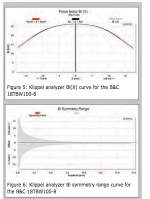
JAG,Here's the B&C 18tbw100 Klippel Bl graph, for those that didn't click the link.
An externally hosted image should be here but it was not working when we last tested it.
Do you have a link to B&C 18SW115 Klippels? Love to see it.
I searched for quite a while and could not find the 18SW115 Klippels, but the first thing in the search found was a reply by Josh Ricci from 2/26/11:
"Really...I did not know that DSL had switched (from the 18 Sound 18nlw9600) to the B&C. Interesting.The top 18" and 21" drivers from both respective companies simulate within a gnats hair of each other in most alignments. There is a full test in Voicecoil mag by Vance D. with Klippel reports for both the 18sw115 and the 18nlw9600 (I figure that you are aware of this but others may not be.). Overall I thought the B&C was very slightly better judging from the symmetry of the BL/x, LE/x, and KMS curves. Both are monsters though.
BTW I have a pair of the B&C 21sw152's and I have a similar "experiment" finding as you did. I free air tested them and they were great up till about 30mm p2p, at about 40mm p2p (guesstimate) they exhibited some motor air flow noise and a little suspension noise. I had the driver connected to a single channel of a QSC pl9.0 run off of 240v and with a 10hz sine wave I was able to drive the amp into clipping without damage to the driver. It seems to brick wall at about 40mm p2p or a little past and further power increases just heat up the coil while not producing appreciably more excursion. The last 3 or so increases in volume did not appear to produce any further cone excursion. Moral of the story is that it seems like you would have to do something really dumb to mechanically damage these drivers. To me it almost appears as if there is a braking action built into the motor perhaps as part of the split winding technique they mention? That is pure speculation on my part. The BL curve is much flatter than a straight overhung design typically is though."
Although at that time I was unaware of "Voice Coil" magazine & Klippel testing, I do recall seeing the B&C 18SW115 Klippel curve, it looked perfectly symmetrical like the B&C 18TBW100 curve you linked, coincidentally the drivers I will be using in the new Keystone "B-Low" version, the driver which I just did the "push-up" test on.
From Josh's quote I'd expect it's BL curve to look like the 18 Sound 18NLW9600 posted below, only symmetrical in both directions.
The non-symmetrical response of the 18NLW9600 may have been responsible for the problems DSL experienced using it in the TH-118 prior to switching to the B&C 18SW115. Ivan Beaver did say 18Sound corrected some adhesive issues which eliminated the "rocking" problems, but without a bit of "history detective" can't determine if the Voice Coil magazine Klippel tests on the 18NLW9600 were the "before" or "after" correction- my rough guess based on recollection of the TH-118 release would be the test was after correction.
Art
Attachments
Last edited:
For a sinewave the maximum acceleration is at crossover/midpoint of stroke.David,
With the inaccuracies inherent with my cone force experiment yesterday, in which I did a "push up" with my hands around the dust-cap of a B&C18TBW100-4, and found the deflection to be approximately 27mm (Xlim) with 98 pounds, that seems to be well within the margin of error to 113.5 pounds.
The 113.5 pounds was on a slightly higher power driver, IIRC, and Hornresp figures BL as linear, even though BL typically is considerably less near and past Xmax. Considering the reduction of BL as the 18TBW100 suspension gets progressively harder to push, it becomes obvious why most failures of this class of speakers are thermal, rather than mechanical.
By the way folks, don't try the "push up" experiment on the typical home theater sealed box sub-woofers, you may cut your hands on the frame spokes when the cone caves in :^).
Art
That should mean that when current is max/peak, then the force is max and the cone will be at midstroke and crossing over.
Does that makes sense?
the force is used to develop pressure in the air load and to accelerate the mass of the cone plus coil/former.
I don't what proportion of the total force goes to accelerating the masses and what goes to pressuring the air.
The bending stress in the former is very low. and that will have a shear stress where the coil is attached.
A conical cone also has a very low bending stress. It's the stretching around it's circumference that resists the accelerating forces and this circumferential stress is quite low.
A profiled cone will develop some bending stress and as it bends the circumferential stress will become significant. It's this "flexible" profile that easily vibrates and also decouples at higher frequencies.
JAG,
I searched for quite a while and could not find the 18SW115 Klippels, ...
Thanks anyway, maybe I'll have a look around when i get some time to waste. I'd like to see the 21sw too, and for that matter the 18tbx ... oh who am I kidding, I'd like to see all of them. Too bad there's not a database or depository for this kind of stuff.
Although at that time I was unaware of "Voice Coil" magazine & Klippel testing, I do recall seeing the B&C 18SW115 Klippel curve, it looked perfectly symmetrical like the B&C 18TBW100 curve you linked, coincidentally the drivers I will be using in the new Keystone "B-Low" version, the driver which I just did the "push-up" test on.
Art
Nice driver choice. The tbw is a bit more affordable than the sw and still a world class driver. Flawless klippels, really a no brainer choice for a a "budget" driver if you only need 14 mm excursion.
I think your new lower tuned Keystone is going to be a big hit. While still tuned a bit high for my taste, it's sure to strike a chord with a lot of people who don't need those lowest notes, as cost vs performance vs size is surely going to be win/win/win.
This is a fascinating thread indeed, good luck to the OP in whatever he decides..
Thanks for all the informative posts and links being presented here guys, great stuff!
Speaking of which, and while not derailing, is there a link to a paper for what you didn't want to go into below, that can describe this in more detail, or should I say expand on the implications?
Thanks
Thanks for all the informative posts and links being presented here guys, great stuff!
Speaking of which, and while not derailing, is there a link to a paper for what you didn't want to go into below, that can describe this in more detail, or should I say expand on the implications?
(Also very interesting to note is that the combined Re of the drivers used in this sim, 5 drivers wired in parallel, is 1.06 ohms. Note that the strong and wide impedance peaks lift the system impedance up to 2x that (well over 2 ohms everywhere in the passband, This is another effect that only full sized horns have - the entire system impedance is higher than the resistance of the drivers used. This has some pretty major implications that I'm not going to discuss right now, but it's a huge benefit.)
An externally hosted image should be here but it was not working when we last tested it.
Thanks
Last edited:
- Status
- This old topic is closed. If you want to reopen this topic, contact a moderator using the "Report Post" button.
- Home
- Loudspeakers
- Subwoofers
- Concrete Bass Horn Design Question