Hi Panson!
thanks for your nice work, I really enjoy reading your tests and comparisons.
At the moment I'm planning my first amp and so I have a few questions:
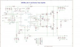
* Why is C13 connected to sink? Nationals AN-1850 shows the compensation cap connected to BiasM.
* I'm planning to use a LME49811 with a double pair of Toshiba 2SA1943/2SC5200 (mostly because they are cheaply available at digikey) and and your MJE1530/1531 pre driver configuration. My intended output-power is 80W/8R0 does this configuration perform well or would you suggest different components?
* Would you like to share the component values of your circuit? Otherwise I'd take the values from AN-1850 and try to calculate the rest on my own. I do have the basics for this, but for sure I'm not the best at this calculations.
* one maybe totally newbie question: what are D6/D7 and L1 for?
thanks for reply,
oliver
thanks for your nice work, I really enjoy reading your tests and comparisons.
At the moment I'm planning my first amp and so I have a few questions:
* Why is C13 connected to sink? Nationals AN-1850 shows the compensation cap connected to BiasM.
* I'm planning to use a LME49811 with a double pair of Toshiba 2SA1943/2SC5200 (mostly because they are cheaply available at digikey) and and your MJE1530/1531 pre driver configuration. My intended output-power is 80W/8R0 does this configuration perform well or would you suggest different components?
* Would you like to share the component values of your circuit? Otherwise I'd take the values from AN-1850 and try to calculate the rest on my own. I do have the basics for this, but for sure I'm not the best at this calculations.
* one maybe totally newbie question: what are D6/D7 and L1 for?
thanks for reply,
oliver
Hi Panson!
thanks for your nice work, I really enjoy reading your tests and comparisons.
At the moment I'm planning my first amp and so I have a few questions:
* Why is C13 connected to sink? Nationals AN-1850 shows the compensation cap connected to BiasM.
* I'm planning to use a LME49811 with a double pair of Toshiba 2SA1943/2SC5200 (mostly because they are cheaply available at digikey) and and your MJE1530/1531 pre driver configuration. My intended output-power is 80W/8R0 does this configuration perform well or would you suggest different components?
* Would you like to share the component values of your circuit? Otherwise I'd take the values from AN-1850 and try to calculate the rest on my own. I do have the basics for this, but for sure I'm not the best at this calculations.
* one maybe totally newbie question: what are D6/D7 and L1 for?
thanks for reply,
oliver
Hi Panson!
thanks for your nice work, I really enjoy reading your tests and comparisons.
At the moment I'm planning my first amp and so I have a few questions:
* Why is C13 connected to sink? Nationals AN-1850 shows the compensation cap connected to BiasM.
* I'm planning to use a LME49811 with a double pair of Toshiba 2SA1943/2SC5200 (mostly because they are cheaply available at digikey) and and your MJE1530/1531 pre driver configuration. My intended output-power is 80W/8R0 does this configuration perform well or would you suggest different components?
* Would you like to share the component values of your circuit? Otherwise I'd take the values from AN-1850 and try to calculate the rest on my own. I do have the basics for this, but for sure I'm not the best at this calculations.
* one maybe totally newbie question: what are D6/D7 and L1 for?
thanks for reply,
oliver
Hi Oliver,
You found a schematic typo. C13 should be connected to BiasM for 49810/49830. I am going to correct this low-tech error. Thank you!
D5/D6 are so-called catching diodes to protect output BJTs in the present of back EMF from the speaker load. They will conduce when that happens.
L1, output coil is used to avoid stability issue in the present of capacitive load.
Two-pair 2SA1943/2SC5200 is very sufficient for 80W into 8 Ohms. These output devices are used in Hi-End equipment like the Luxman M-800A. Good choice! I have some test shown here http://www.diyaudio.com/forums/solid-state/170618-comparing-power-bjts-sanken-semi.html
Please visit my web site and go to Compact 498xx page. You can find a component list there.
Attachments
Last edited:
hi,
have a look at Ostripper's Mongrel.
He uses single sided.
The output module (any one of four different) can be interfaced with any of the voltage amplifier stage modules. Just make a compatible lme4981x module.
Use screw terminals as Os, or pin & socket strips to suit yourself.
have a look at Ostripper's Mongrel.
He uses single sided.
The output module (any one of four different) can be interfaced with any of the voltage amplifier stage modules. Just make a compatible lme4981x module.
Use screw terminals as Os, or pin & socket strips to suit yourself.
Hi Panson, I am experimenting on DIY PCB'ing and would like to make a simple LME49811 thermatrack SINGLE SIDED pcb. Do you have any tips or layouts available?
Hi SuperR,
I don't have any single-sided layout. You use single-side layout because of fab the board yourself.
Separation of small signal (input, NFB) and large signal (decoupling) ground return is very important. The output NFB sample point is also very important too. The decoupling caps should be as close to the associated pins as possible. Don't forget to reserve space of driver chip heatsink.
You can use jumper wires to make your board semi-two layer.
Let us know your progress.
Cheers,
Panson
According to the specsheet of thermaltrak the transistors can operate at a maxium of 150 degrees Celsius. My, assumed to be oversufficient, coolingfins get around 60 degrees Celsius at 20 ambient. Assuming the transistors are <20 degrees Celsius hotter than the colling fins, so 80 degrees Celsius, does that reduce lifetime? They operate well within the safe specs.
Sound is still great tough.
And the idle current for the thermaltrak's doesn't influence the heat dissipation of the LME and driver components right?
Sound is still great tough.
And the idle current for the thermaltrak's doesn't influence the heat dissipation of the LME and driver components right?
Last edited:
have you calculated the temperature de-rated SOAR?According to the specsheet of thermaltrak the transistors can operate at a maxium of 150 degrees Celsius. My, assumed to be oversufficient, coolingfins get around 60 degrees Celsius at 20 ambient. Assuming the transistors are <20 degrees Celsius hotter than the colling fins, so 80 degrees Celsius,
If you have not then how can you claim
Have you looked at the effect of reactive loading on the stress applied to the devices when cold or worse still when hot?They operate well within the safe specs
You have a lot more homework to do before you can "claim" they are "safe".
At say 80 degrees Celsius, 55 over 25 the maximum power dissipation should be 180-78>100 Watt (each) (My torroid can't even deliver such power for all four transistors)
At say 120 degrees Celsius, 95 over 25 the maximum power dissipation should be 180-136>40 Watt (each)
I don't operate at that region of power/temperature.
"Have you looked at the effect of reactive loading on the stress applied to the devices when cold or worse still when hot? " Nope.
What should be interesting literature considering that claim I made based on the power consumption and temperature range?
you have this back to front.(My torroid can't even deliver such power for all four transistors)
The speaker demands a current to satisfy the combination of changing voltages fed to it.
That current flows through the output stage.
The capacitors in the PSU and decoupling store energy just to satisfy that instantaneous demand. The transformer periodically recharges the capacitors to restore the energy bank, about 100/120 times a second for a period of 0.4ms to 1.2ms during each recharge pulse. The majority of the time (about 90 to 95%) the transformer is doing nothing expect dissipating the heat generated from the last recharging pulse.
Last edited:
I am looking for suggestions for designing a new Compact 498xx ThermalTrak board. The followings are being considered.
DC servo
Two-pair output device
Output coil and Zobel network
CFP output
.....
DC servo - not needed
Two-pairs output - YES
Output coil and Zobel network - YES
CFP output - NO, better TRIPLE(for LME49810 drivers and output, for LME49811 predrivers, drivers and output
Better Vbe multiplier, not just ThermalTrak diodes
output BJTs mounted on an alu L bracket on one side, ease to fix to heathsink
dado
LME amp design
Hi panson,
nice to read you again,
during the last weeks I often visited your HP - there I could read your announcement .....amp comming soon...
I'm very interested in properly designed LME pcb's.
Here in the forum I read a lot about LME-amp design.
If you need not more than about 100W/8Ohm, then I prefer a circuit like audioman55 described in our forum:
>>LME49811(class A output) with one pair Sanken STD03N/P
For more power have a look on the circuit from the member opc named "The Wire Amp"
>>LME49830 with single pair of lateral mosfet's ACD101NDD/ACD103PDD (identical with ALF16P20W/ALF16N20W)
This circuit will give you more than 200W/8Ohm.
......two pair output not needed
......output coil and Zobel ok
......DC-servo would be nice,but not needed
......very importand is to have an extra power supply for LME with regulation on board - use a tracking preregulator design with LM317/337,it is cheap,simple and works fine.
......nested feedback loops not needed - keep it simple
regards Harry
- Home
- Amplifiers
- Chip Amps
- Compact Sized LME49810/11 +ThermalTrak Amp