janneman said:Jorge:
I fully, 100%, completely disagree with you.
Is not the first time that someone tell me this in my life...and i hope not the last!
")
I respectfully think you have it the wrong way around.
If everybody agreed with each other...this forum will be very boring...
Jan,
I disagree, if you monitor the voltage it is shunt feedback at the output. If you feedback a current proportional to the voltage it is current feedback, if you feedback a voltage it is voltage feedback. The operation between the two kinds of feedback is rather different and the terms current feedback and voltage feedback are used to define them.
Dave.
Dave,
This is were our ways part. If you feed back (a sample of) the output voltage, it is VF, however you inject the signal in the input stage (current or voltage). Similar to CF (feeding back a sample of the output current).
THAT is the way it is defined, as I thought I demonstrated in earlier posts in this thread. You may have missed them.
Jan Didden
Tube_Dude said:
Is not the first time that someone tell me this in my life...and i hope not the last!
If everybody agreed with each other...this forum will be very boring...
Indeed, and it is one of the less important things in life. I have been proved wrong so often I lose track.
Jan Didden
Re: Re: Current or not ...current....
Hi Jan!
As i was out this weekend i haven't seen this questions.. sorry!
Answer... Current Feedback Current Amplifier!
Answer...Voltage Feedback Current Amplifier!
janneman said:
And, how would you then call a circuit where the output CURRENT sample is injected in a low impedance node?
Hi Jan!
As i was out this weekend i haven't seen this questions.. sorry!
Answer... Current Feedback Current Amplifier!
Better yet, how about a sample of the output current being injected into a high impedance node?
Answer...Voltage Feedback Current Amplifier!
Re: Re: Re: Current or not ...current....
Jan Didden
Tube_Dude said:
Hi Jan!
As i was out this weekend i haven't seen this questions.. sorry!
Answer... Current Feedback Current Amplifier!
Janneman: CF, yes. Current amp, you don't know. Vin may come in in a hi-impedance node. Then it is a voltage controlled current source, actually!
Answer...Voltage Feedback Current Amplifier!
Janneman: No! Current Feedback!
Jan Didden
And what happens if we feed back to the input stage a current proportional to output voltage?
How would we call this? current feedback? voltage feedback? a mixture of both?
I think this is the key to understand these kind of circuits, output voltage gets converted into current before feeding it back to the input
Now imagine an amplifier with current output, how do we sense output current?, would we use a current sense resistor?, then we would have a voltage proportional to output current being feed back to the input stage
How should we call this? current feedback? voltage feedback? a mixture of both?
I think that things are not so simple as to say 'current only' or 'voltage only', any practical amplifier circuit contains both voltage and current feedbacks
In the real world theories have to be carefully understood since a single transistor may be acting as a V to I converter at low frequencies and as a I to V at high frequencies [due to beta reduction, miller effect and local feedback]
So think abount an amplifier circuit with 4 or 6 transistors in signal path, this means lots of V/I and I/V conversions and lots of V and I local and global feedbacks
In this circuit from Elektor there is a feedback loop between the output drivers and IGBTs, another local feedback in the 'VAS' and a global feedback loop, the behavior of all three loops is dependent on frequency, this is not so simple as those 'black boxes with gain' used in theory books [and notice I'm not mentioning local feedback used on each transistor in the circuit]
Eva said:And what happens if we feed back to the input stage a current proportional to output voltage?
How would we call this? current feedback? voltage feedback? a mixture of both
Olá Eva!
I call this a current feedback voltage amplifier!
Now imagine an amplifier with current output, how do we sense output current?, would we use a current sense resistor?, then we would have a voltage proportional to output current being feed back to the input stage
~How should we call this? current feedback? voltage feedback? a mixture of both?
Is a current amp as you are sampling output current...and if the summing nod is a low impedance, you have a current feedback current amplifier, but if this summing node has high impedance you have a voltage feedback current amplifier...
Saludos cordiales!
VF and CF defined by Paul M. Chirlian
From "Analysis and Design of Integrated Electronic Circuits" by Paul M. Chirlian 1987 page 811:
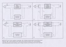
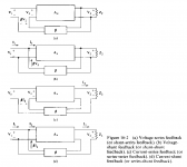
"We have classified feedback as positive or negative. Let us consider some additional classifications. There is 'voltage feedback' and 'current feedback'. In voltage feedback, the signal fed back (which can be either a voltage or a current) is proportional to the output voltage, whereas in current feedback, the signal fed back is proportional to the output current. When voltage negative feedback is used, the output voltage tends to become independant of the value of Av, whereas current negative feedback tends to stabilize the output current. ...Block diagrams for voltage and current feedback are shown in Fig. 16-2. Figures 16-2a and 16-2b represent voltage feedback since the signal fed back is proportional to the output voltage. Now, look at the inputs to the amplifiers. In Fig. 16-2a the feedback signal is placed in series with the input signal, so V3=V1+bV2
This is called 'series feedback'. In Fig. 16-2b, the feedback signal is in parallel (shunt) with the input. Now we consider that the feedback signal is a current that is proportional to the output voltage. This is called 'shunt feedback' I3=I2+bV2
In this case b is not dimensionless. Its units are mhos. Note that V3=V1 in this case. This implies that, if the input generator has no series impedance, then there is no feedback. Note that the amplifier of Fig. 13-4 used voltage shunt feedback. In that case, the resistor R1 could be considered to be the generator resistance.
In Figs. 16-2c and 16-2d we have examples of current feedback. Now the feedback signal is proportional to the load current. Figure 16-2c is an example of 'current series feedback'. Here the feedback signal is a voltage that is proportional to the output current. Figure 16-2d represents 'current shunt feedback'. Note the in Fig. 16-2c the units of b are ohms while in Fig. 16-2d, b is dimensionless. When voltage feedback is used the input to the b network is placed in parallel with the output. Thus the word shunt can be used to replace voltage. For instance voltage-series feedback can be called shunt-series feedback and voltage-shunt feedback can be called shunt-shunt feedback. In a similar way current-series feedback can be called series-series feedback and current-shunt feedback can be called series-shunt feedback.
From "Analysis and Design of Integrated Electronic Circuits" by Paul M. Chirlian 1987 page 811:
"We have classified feedback as positive or negative. Let us consider some additional classifications. There is 'voltage feedback' and 'current feedback'. In voltage feedback, the signal fed back (which can be either a voltage or a current) is proportional to the output voltage, whereas in current feedback, the signal fed back is proportional to the output current. When voltage negative feedback is used, the output voltage tends to become independant of the value of Av, whereas current negative feedback tends to stabilize the output current. ...Block diagrams for voltage and current feedback are shown in Fig. 16-2. Figures 16-2a and 16-2b represent voltage feedback since the signal fed back is proportional to the output voltage. Now, look at the inputs to the amplifiers. In Fig. 16-2a the feedback signal is placed in series with the input signal, so V3=V1+bV2
This is called 'series feedback'. In Fig. 16-2b, the feedback signal is in parallel (shunt) with the input. Now we consider that the feedback signal is a current that is proportional to the output voltage. This is called 'shunt feedback' I3=I2+bV2
In this case b is not dimensionless. Its units are mhos. Note that V3=V1 in this case. This implies that, if the input generator has no series impedance, then there is no feedback. Note that the amplifier of Fig. 13-4 used voltage shunt feedback. In that case, the resistor R1 could be considered to be the generator resistance.
In Figs. 16-2c and 16-2d we have examples of current feedback. Now the feedback signal is proportional to the load current. Figure 16-2c is an example of 'current series feedback'. Here the feedback signal is a voltage that is proportional to the output current. Figure 16-2d represents 'current shunt feedback'. Note the in Fig. 16-2c the units of b are ohms while in Fig. 16-2d, b is dimensionless. When voltage feedback is used the input to the b network is placed in parallel with the output. Thus the word shunt can be used to replace voltage. For instance voltage-series feedback can be called shunt-series feedback and voltage-shunt feedback can be called shunt-shunt feedback. In a similar way current-series feedback can be called series-series feedback and current-shunt feedback can be called series-shunt feedback.

more feedback
Checked a few more analog books about VF and CF.
Sedra and Smith avoid term
Laker and Sansen avoid term
Grebene avoids term
all above use the series-shunt definitions
J. Watson uses "voltage derived feedback" and "current derived feedback" I LIKE his approach, better than long word like V/C - information feedback.
looks like Sergio Franco might be the guy who redefined feedback as relevent to the input side, EDN 1989 Jan. -- arrest this guy!--
IGBT? Nee!!
May this be my first contribution to diyAudio (member since a day or three):
I refer to the very first question asked in this thread: "has anyone built the Elector Compact Amp?"
Yes I did.
The original article was published in Elektor, may 1997. Only 2 months ago (dec 2003) I started the Compact Amp project, and finished it two weeks ago.
Main conclusion: the bl@#$% thing doesn't work with IGBT's.
After building the amp exactly to specifications (I used GT20D101/~201 from Toshiba), and with much care, testing it resulted in the following 2 problems, the 1st minor, and the 2nd major:
1. off-set voltage was, in my case, not about 0 Volts, but some 500 mV. To shortcut a long story: base-emitter voltage of the input stage transistors (T1 and T2, BC 550C/560C) should be exactly the same, otherwise the correction circuit with OP77 becomes out of reach, and off-set in the output results. I paired the Tr's to be equal within the 3rd decimal, but appearently not yet sufficiently. I solved this problem by lowering R42 from 8k2 to some 7k, so the OP177 (OP77 no longer available, but OP177 replaced it) could deliver a higher current, this time sufficiently enough to correct the off-set (current now is some 3 mA, according to specifications OP177 can deliver 40 or more mA, so this should give no problems).
2. idle-current should be, according to Elektor, about 400 mA. I used Ammeters in both feed leads, so I could monitor what happened while adjusting idle-current. When I reached 400 or 500 mA, my mA-meters suddenly jumped out of reach of the scale. I guess current raised to some 3 to 5 A, but never gave it a long time (fear of blowing my IGBT's). I reproduced this process several times.
To, in spite of al this, continue my project, I adjusted idle-current to a low value, some 50-100 mA. Then I connected the amp to a music source, and a loudspeaker, and played some music (still with the Ammeters in the line feed). What did I observe: the ammeters followed the music signal, as if it where VU meters. (Idle?)current jumped from peak to peak, and when I played louder, they, again, jumped out of scale, and seemed to be "stuck".
A failure project. Or...?
I remembered earlier Elektor projects, the "Hexfet power amp" of 1993 and the "IGBT" of 1995. By the way, I also built these amps, but after years of, alternating, listening pleasure and amp-problems, I broke them down, (but that's another story). However, both these amps were practically identical in circuit design, except for the power-transistors. So why not try to put in a pair of Hexfet's (I had several in stock from my former project).
I replaced the IGBT's by hexfet's (IRF540/9540), and: all worked well!!!
No problems with jumping idle-current (I adjusted it to some 250 mA), when playing music I hardly could see the ammeters moving (played very loudly some increase in current).
So now, since a week, I listen to my newly built pride. Sound quality seems to be OK in all respects.
To end with some remarks on sound quality: 2 years ago I built Elektors "crescendo millennium" , a mosfet power amp, published april 2001. This was a project giving no problems at all, and I played it for the last two years. In the article Elektor compares sound quality of the Crescendo to the Compact amp, and judges the Compact amp to be more "analytical", the Crescendo more "laid back, warm". So far I fully agree on this. The Compact amp sometimes even seems to be a little too analytical to my ears: especially with string quartets (mainly I play classical) sound sometimes seems to be a little sharp. Maybe I must get more accustomed to the sound to better appreciate it. However, when forced to make a choice at this very moment I'd give preference to the Crescendo.
Re: IGBT? Nee!!
Yeah. I often looked at the circuit diagram, wondering what is controlling Iq. It's reassuring that your practical experiments confirmed: nothing controls Iq.
I'll put together what's wrong there, and how I would change it.
Regards,
Peter Jacobi
kramer said:[...]
2. idle-current should be, according to Elektor, about 400 mA. I used Ammeters in both feed leads, so I could monitor what happened while adjusting idle-current. When I reached 400 or 500 mA, my mA-meters suddenly jumped out of reach of the scale. I guess current raised to some 3 to 5 A, but never gave it a long time (fear of blowing my IGBT's). [...]
Yeah. I often looked at the circuit diagram, wondering what is controlling Iq. It's reassuring that your practical experiments confirmed: nothing controls Iq.
I'll put together what's wrong there, and how I would change it.
Regards,
Peter Jacobi
IGBT? Perhaps so...
Look at this proposed modification of the output stage:
http://www.linearaudio.de/scratch/CPA-1.pdf
Looks unfamiliar? You'll recognize the MJE15030/15031 drivers. Start looking there.
The darlingtons+diode are rough approximations for the IGBTs in my simulator (I don't have complementary IGBT models).
Compare with the topology of the original output stage:
http://www.linearaudio.de/scratch/CPA-2.pdf
In CPA-2, the drivers doesn't sense the current through the power devices. In CPA-1, R1 and R2 will send this information to the emitters of the drivers.
Regards,
Peter Jacobi
LTSpice circuit files:
http://www.linearaudio.de/scratch/CPA-1.asc
http://www.linearaudio.de/scratch/CPA-2.asc
pjacobi said:I'll put together what's wrong there, and how I would change it.
Look at this proposed modification of the output stage:
http://www.linearaudio.de/scratch/CPA-1.pdf
Looks unfamiliar? You'll recognize the MJE15030/15031 drivers. Start looking there.
The darlingtons+diode are rough approximations for the IGBTs in my simulator (I don't have complementary IGBT models).
Compare with the topology of the original output stage:
http://www.linearaudio.de/scratch/CPA-2.pdf
In CPA-2, the drivers doesn't sense the current through the power devices. In CPA-1, R1 and R2 will send this information to the emitters of the drivers.
Regards,
Peter Jacobi
LTSpice circuit files:
http://www.linearaudio.de/scratch/CPA-1.asc
http://www.linearaudio.de/scratch/CPA-2.asc
jazzpeter65 said:I have suddently four GT20D101/~201 from Toshiba for sale.....
I'll take them. Email me your price.
OTOH, you can try the proposed modification.
Or, put together some low device count, SE class A amp. The Zen of IGBTs, so to speak.
I am the proud owner of 10 Infineon IGBTs as I couldn't resist a very low price on eBay. I'll try the Z.o.IGBT path, especially as I'm only having n-types of course...
Regards,
Peter Jacobi
- Status
- This old topic is closed. If you want to reopen this topic, contact a moderator using the "Report Post" button.
- Home
- Amplifiers
- Solid State
- Compact Power Amplifier from Elektor