Oooops...sorry about that.Indeed I have seen that avs thread, in fact I just posted a link to it in my last post.

I got the AVS and diyAudio threads swapped. Here is the link I should have posted:
http://www.diyaudio.com/forums/subwoofers/277267-multi-sub-optimizer-2.html#post4823395
The O-scope trace talk with bentoronto reminded me I meant to comment on several of your posts where you suggested that MFB would require more power to force drivers to behavior in a linear fashion. I willingly admit that this was exactly what I had thought…until I actually built a MFB system and looked at O-scope traces. If you look at the waveform distortion generated by woofers operating beyond Xmax, the sinewave shape does not get clipped or tend to flat-top the way you might expect. Rather, you will see a triangular shape(3rd harmonic like square wave, but opposite sine). This puzzled my for quite some time before stumbling on an old Wireless World article that explained why(I’ll post it if I can find it). Basically it boils down to the phase difference between force application and cone acceleration(SPL) and operating in stiffness dominated range below resonance. With matched magnitude of fundamental, the waveform actually peaks at amplitudes higher than with no distortion. So, if distortion is predominately 3rd harmonic the woofer is actually driven less hard by MFB at particular times in order to clean up the distortion and leave the same level of fundamental. Power requirement for reducing 2nd harmonic is less clear, but in general terms MFB requires a little more drive during half the period, and a little less during the other. In any case, the differences in amplitude we are talking about is pretty minor. The take-home is that low frequency distortion reduction by MFB does not require significantly more power or generate more VC heat to produce the same fundamental SPL as a non-MFB system.
The distortion levels shown in the attached waveforms were about 20% without MFB, and 8% with MFB. This was from a VC feedback system, showing about 3x reduction, which is typically about as good as I could get with VC feedback. I know I’ve seen pics of an even better comparison(not mine) here on diyAudio(I think) where there was significantly more distortion and much more 2nd harmonic. Will see if I can track that down…
On the topic of woofer distortion and drive level, meant to comment on this as well.
In my experience, distortion tends to increase at a fairly moderate rate. In this case they increased output by ~9.5dB, so ~3x applied voltage, ~9x applied power, and the distortion only went up by about 2x. So, not exactly an exponential rate relative to increased voltage or power. I don’t think you’ll see exponential behavior until suspension starts reaching end of throw limits.If there was another chart showing distortion levels at 90 db, the distortion levels would be VERY low, as the distortion is ramping up at exponential rates with increased power level.
Attachments
Great to have more data points from bolserst.
While the attached traces show how much cleaner the VC MF performance is, hard to intuit how bad that is perceptually or, at least for me, to connect the wavy lines to %THD numbers.
For sure on acoustic music, you can have lots of harmonic distortion without being annoyed. Some musicians add distortion (which seems jarring to me).
But think of it this way - which also happens to relate to programs for locating your subs*. First of all, with the Fletcher-Munson phenomenon, harmonics at say 90 and above are vastly easier to hear. And likewise, easier to locate spatially. So the distortion products of your sub screw up the stereo image.**
I think managing the freq response through and below resonance and making for fast bass are bigger issues than distortion. But easier to measure and talk about distortion, as bolserst helpfully has - now with a nod to VC feedback, eh.
Ben
*for along time I've advocated having a DIY acoustics (which really means psychoacoustics) here
**like wheezy BR vents
The O-scope trace talk with bentoronto reminded me I meant to comment on several of your posts where you suggested that MFB would require more power to force drivers to behavior in a linear fashion. I willingly admit that this was exactly what I had thought…until I actually built a MFB system and looked at O-scope traces. If you look at the waveform distortion generated by woofers operating beyond Xmax, the sinewave shape does not get clipped or tend to flat-top the way you might expect. Rather, you will see a triangular shape(3rd harmonic like square wave, but opposite sine). This puzzled my for quite some time before stumbling on an old Wireless World article that explained why(I’ll post it if I can find it). Basically it boils down to the phase difference between force application and cone acceleration(SPL) and operating in stiffness dominated range below resonance. With matched magnitude of fundamental, the waveform actually peaks at amplitudes higher than with no distortion. So, if distortion is predominately 3rd harmonic the woofer is actually driven less hard by MFB at particular times in order to clean up the distortion and leave the same level of fundamental. Power requirement for reducing 2nd harmonic is less clear, but in general terms MFB requires a little more drive during half the period, and a little less during the other. In any case, the differences in amplitude we are talking about is pretty minor. The take-home is that low frequency distortion reduction by MFB does not require significantly more power or generate more VC heat to produce the same fundamental SPL as a non-MFB system.
So when a driver is pushed into the suspension limits zone and it gets vastly harder to push because it can only stretch so far and it gets stiffer at the limits, AND at the same time the coil is running out of the gap so the Bl is a fraction of it's resting value, AND at the same time the driver is thermally stressed so that Re has increased, so impedance is different (more voltage is required for the same excursion) native frequency response (before MF) is entirely different than at low power so some frequencies require more boost, you are saying it doesn't require more power for MF to correct this situation and push the cone into territories it doesn't want to go to properly and accurately reproduce the waveform? (That's 3 totally different but concurrent points of problems, but still, life is hard on the edge when you push it.)
You did underline "same fundamental SPL as a non-MFB system", but to be clear, my whole point was that a non-MF system shouldn't even be attempting to operate in those conditions (you should add more drivers instead to make up for the extra spl you need)- for that matter IMO a MF shouldn't be doing it either, but at least it can attempt to do so and with some degree of competency, and that operation at the extremes is a highly touted benefit of MF, in fact manufacturers can't stop talking about how great their products handle this type of abuse.
Just want to be clear here, but it seems impossible that forcibly driving the cone to it's stiff suspension limits and the coil to the edge of the gap and maybe clear out of the gap wouldn't take more power. A non-MF system wouldn't even attempt to keep it linear - it would just provide it's regular amount of force and the cone simply wouldn't follow the waveform accurately. The MF system would have to add power to keep the cone following the waveform accurately under these conditions, no?
Last edited:
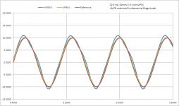
The no-MFB blue curve was @ 20% distortion and took on a blurry nature to the sound of the tone. The with-MFB green curve was @8% distortion and sounded like a pure tone to me by comparison. For me personally , 5%-10% seems to be the threshold that I start noticing obvious “thickening” of a 20Hz tone.While the attached traces show how much cleaner the VC MF performance is, hard to intuit how bad that is perceptually or, at least for me, to connect the wavy lines to %THD numbers.
You bet!- now with a nod to VC feedback, eh.
VC MFB is fun and educational to play with. You just need to be realistic about its limitations.
As I have said several times in this thread and the other MFB threads, VC feedback can reduce distortion at the low end of the frequency range by(2x – 3x)where the compliance distortion is greater than the magnetic distortion. Up at 40Hz to 80Hz, VC feedback provided no benefit in distortion reduction…often even increasing the distortion a bit. It does provide the response flattening desired though. If you want 10x or more distortion reduction across the 20Hz to 80Hz range, you will need to use a sensor that is more linear than a VC.
Also I forgot the air spring, the air spring gets harder to push as excursion increases.
So you've got 4 concurrent problems at high excursion and power levels.
- air spring gets harder to push
- suspension gets harder to push
- Bl get dramatically lowered
- thermal issues cause impedance and frequency response to change
It would intuitively seem that the only way to counter any of those issues would be to add more power.
I understand the 4 points you mention as potential problems, although I think only 1 is of real concern.
My post was concerning BL tapering, although moderate suspension stiffness increase is included since all woofers have it to some extent. All that was being illustrated was that the tapering off of BL does not necessarily mandate a significant additional voltage input to the woofer to correct the resulting distortion…as odd as that may seem. Then again, looking at triangle waves coming from your woofer when intuition says they should be flat-topped squarish looking waves(like when tube amps clip) is pretty odd too.
The additional thermal stress from driving a single woofer harder than you would a multi-woofer system is a very real concern. It must be considered when sizing the amp and the intended use. It is no coincidence that subwoofers intended for concert or dance hall use have higher long term thermal capability than those intended for hi-fi use.
I’m not sure about what happens if you have a woofer with a particularly steep increase in suspension stiffness when stroke starts exceeds Xmax(based on BL). That is not a type of woofer I would ever choose for a MFB project…or any hi-fi project for that matter. If the suspension stiffness is that nonlinear, why would you use it at all?...perhaps to keep auto-boom-boom types from overstroking and destroying it? If you wanted to keep distortion below audible thresholds without MFB, you would have to avoid stroke that reached the steep increase point. If I can locate a woofer like this I can borrow, I will give it a test-drive beyond the threshold with MFB, for science….well that and morbid curiosity.
The air-spring will get harder to push with increasing stroke…that is the very definition of a spring F=K*x. But, the change in the spring constant(K) during a complete in-out cycle which would cause distortion is comparatively small once you crunch the numbers. Also, since this variation in K during the stroke results in 2nd harmonic distortion, it wouldn’t require additional net power to overcome anyways.
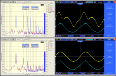
I did locate the higher distortion plots I was thinking of.
The first attachment shows harmonic content and wave forms with and without MFB for matched fundamental amplitude.
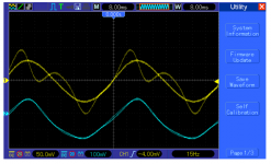
The second attachment is an overlay of the waveforms so you can see more clearly the differences in input voltage(blue curve) and output SPL(yellow curve).
Looking at the peaky, kinked no-MFB output, you would never guess the minute changes to input voltage required to clean it up from 67% to 5% THD.
My post was concerning BL tapering, although moderate suspension stiffness increase is included since all woofers have it to some extent. All that was being illustrated was that the tapering off of BL does not necessarily mandate a significant additional voltage input to the woofer to correct the resulting distortion…as odd as that may seem. Then again, looking at triangle waves coming from your woofer when intuition says they should be flat-topped squarish looking waves(like when tube amps clip) is pretty odd too.
The additional thermal stress from driving a single woofer harder than you would a multi-woofer system is a very real concern. It must be considered when sizing the amp and the intended use. It is no coincidence that subwoofers intended for concert or dance hall use have higher long term thermal capability than those intended for hi-fi use.
I’m not sure about what happens if you have a woofer with a particularly steep increase in suspension stiffness when stroke starts exceeds Xmax(based on BL). That is not a type of woofer I would ever choose for a MFB project…or any hi-fi project for that matter. If the suspension stiffness is that nonlinear, why would you use it at all?...perhaps to keep auto-boom-boom types from overstroking and destroying it? If you wanted to keep distortion below audible thresholds without MFB, you would have to avoid stroke that reached the steep increase point. If I can locate a woofer like this I can borrow, I will give it a test-drive beyond the threshold with MFB, for science….well that and morbid curiosity.
The air-spring will get harder to push with increasing stroke…that is the very definition of a spring F=K*x. But, the change in the spring constant(K) during a complete in-out cycle which would cause distortion is comparatively small once you crunch the numbers. Also, since this variation in K during the stroke results in 2nd harmonic distortion, it wouldn’t require additional net power to overcome anyways.
I did locate the higher distortion plots I was thinking of.
The first attachment shows harmonic content and wave forms with and without MFB for matched fundamental amplitude.
The second attachment is an overlay of the waveforms so you can see more clearly the differences in input voltage(blue curve) and output SPL(yellow curve).
Looking at the peaky, kinked no-MFB output, you would never guess the minute changes to input voltage required to clean it up from 67% to 5% THD.
Attachments
This is the kind of situation I was talking about - data-bass commentary on the B&C 21sw152.
All soft bottom designs are like this, they can't hit xmech because either the force (Bl) or the suspension or both won't allow it. This soft limit is well past xmax but in the region between xmax and the soft bottom it has to be getting increasingly non linear. I seriously doubt it goes to 19 mm in linear fashion and then just stops going any further when it hits 20 mm regardless of how much power you force feed it.
Intuitively, pushing an air spring or a suspension past it's linear region where it gets increasingly stiffer, farther than it wants to go, HAS to require more power.
(The only reason I even mentioned the air spring was because one of the usual primary goals of MF is small box size, and if it gets too small the spring becomes harder to push, as verified by the patent TB46 posted earlier. As that paper hints it's not a big problem with reasonably sized boxes but when small box size is a priority it can be quite a substantial issue requiring a lot of power to push through.)
Intuitively, decreased Bl as the coil reaches the end of the gap has to require more power. You say it doesn't but I wonder how far the system under test was pushed? At some point, if the coil leaves the gap completely and leaves the magnetic field there will be no Bl at all. That would be a very extreme case but somewhere between the flat linear portion of the Bl curve and the point that the coil is completely out of the magnetic field (which may not be physically possible but used here as an extreme example) there has to be a point where Bl is very low and extra power is required from a MF system to maintain linearity. In the quote it seems like data-bass is assuming a large part of the soft bottom in that particular driver is low Bl.
Regarding thermal stress, since small box size and pushing a driver past it's linear region are common MF goals, thermal compression is almost guaranteed, even if you use pro type high power drivers. When things get hot Re is increased, increased Re requires additional Eg to maintain the same power (watts). Heat accumulates with time and the situation continues to get worse and worse, requiring more and more voltage to make the same amount of watts. At some point you run out of available voltage or the driver gets too hot and fails catastrophically. This is one of the first things I learned on this forum and I have a healthy respect for this issue, preferring to design to mitigate the issue by using efficient (large) enclosures and sizing the system properly so individual drivers never get thermally stressed. MF, with it's oft times small enclosures and ability to push the drivers well out of their linear region with low distortion is a recipe for thermal problems even with state of the art high power drivers.
This is all purely academic to me, as pushing drivers to this type of abuse is completely contrary to everything I believe in as far as proper design, so I have done no tests nor will I. But looking at these extreme examples (Bl reduced to almost 0, thermal rise to near the breaking point, suspension pushed to it's physical limits, the tight air spring of a much too small box), I remain skeptical that any of these things can be overcome without adding more power to keep the cone acting in linear fashion to accurately follow the waveform.
At about 18 to 20mm of excursion in one direction the cone will simply not go any further despite further increases in power. The gap geometry indicates that the voice coil is almost completely out of the gap at 20mm one way, which will result in drastically reduced motor force and the suspension is likely becoming incredibly stiff as well. The mechanical clearance before something hard bottoms is listed at 30mm. The driver could not be bottomed out or pushed further than roughly 20mm one way excursion even in free air, at very high voltage levels at 10 cycles.
All soft bottom designs are like this, they can't hit xmech because either the force (Bl) or the suspension or both won't allow it. This soft limit is well past xmax but in the region between xmax and the soft bottom it has to be getting increasingly non linear. I seriously doubt it goes to 19 mm in linear fashion and then just stops going any further when it hits 20 mm regardless of how much power you force feed it.
Intuitively, pushing an air spring or a suspension past it's linear region where it gets increasingly stiffer, farther than it wants to go, HAS to require more power.
(The only reason I even mentioned the air spring was because one of the usual primary goals of MF is small box size, and if it gets too small the spring becomes harder to push, as verified by the patent TB46 posted earlier. As that paper hints it's not a big problem with reasonably sized boxes but when small box size is a priority it can be quite a substantial issue requiring a lot of power to push through.)
Intuitively, decreased Bl as the coil reaches the end of the gap has to require more power. You say it doesn't but I wonder how far the system under test was pushed? At some point, if the coil leaves the gap completely and leaves the magnetic field there will be no Bl at all. That would be a very extreme case but somewhere between the flat linear portion of the Bl curve and the point that the coil is completely out of the magnetic field (which may not be physically possible but used here as an extreme example) there has to be a point where Bl is very low and extra power is required from a MF system to maintain linearity. In the quote it seems like data-bass is assuming a large part of the soft bottom in that particular driver is low Bl.
Regarding thermal stress, since small box size and pushing a driver past it's linear region are common MF goals, thermal compression is almost guaranteed, even if you use pro type high power drivers. When things get hot Re is increased, increased Re requires additional Eg to maintain the same power (watts). Heat accumulates with time and the situation continues to get worse and worse, requiring more and more voltage to make the same amount of watts. At some point you run out of available voltage or the driver gets too hot and fails catastrophically. This is one of the first things I learned on this forum and I have a healthy respect for this issue, preferring to design to mitigate the issue by using efficient (large) enclosures and sizing the system properly so individual drivers never get thermally stressed. MF, with it's oft times small enclosures and ability to push the drivers well out of their linear region with low distortion is a recipe for thermal problems even with state of the art high power drivers.
This is all purely academic to me, as pushing drivers to this type of abuse is completely contrary to everything I believe in as far as proper design, so I have done no tests nor will I. But looking at these extreme examples (Bl reduced to almost 0, thermal rise to near the breaking point, suspension pushed to it's physical limits, the tight air spring of a much too small box), I remain skeptical that any of these things can be overcome without adding more power to keep the cone acting in linear fashion to accurately follow the waveform.
Last edited:
Intuitively, decreased Bl as the coil reaches the end of the gap has to require more power. You say it doesn't but I wonder how far the system under test was pushed? At some point, if the coil leaves the gap completely and leaves the magnetic field there will be no Bl at all. That would be a very extreme case but somewhere between the flat linear portion of the Bl curve and the point that the coil is completely out of the magnetic field (which may not be physically possible but used here as an extreme example) there has to be a point where Bl is very low and extra power is required from a MF system to maintain linearity. In the quote it seems like data-bass is assuming a large part of the soft bottom in that particular driver is low Bl.
I did not read the whole thread so I am not sure that the effect on a standard (non servo) driver of the Bl decrease at the end of the gap has been discussed.
When the coil appoaches the end of the gap, the BL decreases.
So the back-EMF is less, the impedance lowers, leading to more current in the voice-coil and more force on the cone. Consequently, there is a tendancy of the voice-coil to be pushed out of the gap. This effect called instability ot the driver is currently often forgotten.
Doesn't your use of "a bit" really mean "...distortion might deteriorate a little at some odd frequency or two", rather than "...VC MFB makes distortion a little worse across the band"?Up at 40Hz to 80Hz, VC feedback provided no benefit in distortion reduction…often even increasing the distortion a bit
Those alternatives to "a bit" convey very different impressions of distortion improvement with VC methods.
What do you suppose is going on at those frequencies?
Likewise, apropos those wonderful charts you posted (a few posts after), what is the mechanistic explanation for the hideous 15 Hz non-MFB waveform and why does such a tiny change to the MFB signal make so much difference?
B.
Might try to answer my own question.Likewise, apropos those wonderful charts you posted (a few posts after), what is the mechanistic explanation for the hideous 15 Hz non-MFB waveform and why does such a tiny change to the MFB signal make so much difference?
I guess what we are seeing with the hideous non-MFB wave is that all those higher frequency distortion notes are piling up early in the wave form (they pile up early because they are faster). So there is a peak before the true wave peak and there is a lowering after the true wave peak.
But still mysterious how such a small change in the MFB drive signal can make such a big change in the audio output waveform?
BTW, in 5 minutes, anybody can eyeball their speaker error - no mic needed. Just connect a small resistor (.5 or 1 Ohm) to your speaker ground-side terminal and do an REW sweep of the electric signal. It will also reveal distortion and your speaker resonances will be obvious. And you may even see the VC inductance show up at higher frequencies.
Simple as that. You are looking at your rudimentary VC MFB signal!
Ben
Last edited:
Bolserst,With matched magnitude of fundamental, the waveform actually peaks at amplitudes higher than with no distortion. So, if distortion is predominately 3rd harmonic the woofer is actually driven less hard by MFB at particular times in order to clean up the distortion and leave the same level of fundamental. Power requirement for reducing 2nd harmonic is less clear, but in general terms MFB requires a little more drive during half the period, and a little less during the other. In any case, the differences in amplitude we are talking about is pretty minor.
1)The take-home is that low frequency distortion reduction by MFB does not require significantly more power or generate more VC heat to produce the same fundamental SPL as a non-MFB system.
2)My post was concerning BL tapering, although moderate suspension stiffness increase is included since all woofers have it to some extent. All that was being illustrated was that the tapering off of BL does not necessarily mandate a significant additional voltage input to the woofer to correct the resulting distortion…as odd as that may seem. Then again, looking at triangle waves coming from your woofer when intuition says they should be flat-topped squarish looking waves(like when tube amps clip) is pretty odd too.
3)The additional thermal stress from driving a single woofer harder than you would a multi-woofer system is a very real concern. It must be considered when sizing the amp and the intended use. It is no coincidence that subwoofers intended for concert or dance hall use have higher long term thermal capability than those intended for hi-fi use.
4)I’m not sure about what happens if you have a woofer with a particularly steep increase in suspension stiffness when stroke starts exceeds Xmax(based on BL). That is not a type of woofer I would ever choose for a MFB project…or any hi-fi project for that matter. If the suspension stiffness is that nonlinear, why would you use it at all?...perhaps to keep auto-boom-boom types from overstroking and destroying it? If you wanted to keep distortion below audible thresholds without MFB, you would have to avoid stroke that reached the steep increase point. If I can locate a woofer like this I can borrow, I will give it a test-drive beyond the threshold with MFB, for science….well that and morbid curiosity.
5)The air-spring will get harder to push with increasing stroke…that is the very definition of a spring F=K*x. But, the change in the spring constant(K) during a complete in-out cycle which would cause distortion is comparatively small once you crunch the numbers. Also, since this variation in K during the stroke results in 2nd harmonic distortion, it wouldn’t require additional net power to overcome anyways.
6)The first attachment shows harmonic content and wave forms with and without MFB for matched fundamental amplitude.
The second attachment is an overlay of the waveforms so you can see more clearly the differences in input voltage(blue curve) and output SPL(yellow curve).
Looking at the peaky, kinked no-MFB output, you would never guess the minute changes to input voltage required to clean it up from 67% to 5% THD.
Thanks for providing useful data and observations.
1) Very important point for portable systems-we don't want to transport anything larger/heavier than needed, just enough "rig for the gig". For home systems size factor is probably at least as important, with your friends who find any sub larger than a breadbox "too big". Also, with class D amplifiers like those used in the IPAL system, the back EMF force from the driver can be partially "recycled", allowing for more amplifier output with less power drawn from the power source.
2) That observation is interesting, but no longer counter intuitive since I found out a decade or so ago (when JR handed me my yass on a platter in his explanation ;^) ) that square waves can only make a cone/diaphragm "stand still" when within the linear operating range, and when more than one tone is applied, as in music, the cone/diaphragm never will "stand still".
3) Since concert speakers must withstand the thermal stress generated by the additional heat from direct sunlight and operating at "full tilt boogie" for 12 hours or more at a time, definitely no coincidence, and in many cases thermal considerations are prime, the speaker must "win" in the amp power/Pmax war that has been going on since the beginning of the PA business (around one century and counting..), or the system is compromised, or makes no sound at all.
4) A "non-linear" suspension, ie one that becomes progressively stiffer beyond Xmax can mechanically provide a "safety net" when users decide to drive it below Fb, or drive it well above Xmax. It is obvious to anyone looking at a burnt voice coil that Pmax was exceeded, but Xmech failures are a little harder to sort out- perhaps a failed glue joint was responsible, or perhaps the driver was driven below Fb, equivalent to open air operation with 10,000 watts- no burnt coil, warranty might still be honored by reputable manufacturers.
5)Continuing with my defense of "stiff" drivers, once past Xmax/Xvar(measured linear BL response) the motor is basically incapable of doing much damage, either mechanically or audibly. As an example, while testing a B&C 18SW115-4 (a four ohm driver) with a 60 Hz sine wave, I mistakenly subjected it to 120 volts (likely clipped to a square wave, 100% duty cycle) four times in a row, causing the amplifier's breaker to open each time before figuring out I was turning down the crossover's "high" output instead of the "low" output. If this had been one of the "floppy" suspensions with an overhung voice coil, the 3600+ watts applied would have flattened the voice coil like a run-over hat. As it was, other than the surprise of the 130+ dB SPL output (I had my near-sighted eyes within a few inches of the cone to measure excursion the first time) the driver did not sound very distressed at all, and no mechanical (or thermal) problems resulted.
6) In my opinion, since the majority of people taking the Klippel distortion tests
http://www.klippel-listeningtest.de/lt/
can't hear low frequency distortion (of any type) below 100 Hz until it reaches 2 digit THD, reduction below that level is a pursuit with diminishing returns on the $$ required to achieve it, since by (the better) definition, driving a speaker to Xmax only results in 10% THD.
In regards to Ben's observation "Some musicians add distortion (which seems jarring to me)", I would remind him that many electronic instruments are lacking in the upper harmonics many acoustic instruments, (and pipe organs..) contain, and using tube (valve) amps add primarily even order distortion, which is always musically appropriate, as it never results in notes not in the original composition, and can be pleasant sounding even when exceeding 100%.
That is not to say that many distortion types used by musicians or recording engineers are always even order, or "pleasing"- there have been odd order "fuzz boxes" available for several generations now, each new generation managing to find some new sound guaranteed to diss off their parents, unless their parents happen to be open-minded to "new music".
Art
Last edited:
Here we go, using 2.2 Ohm resistor connected to a 15-inch, 8 Ohm driver in a 6 cu ft sealed box.BTW, in 5 minutes, anybody can eyeball their speaker error - no mic needed. Just connect a small resistor (.5 or 1 Ohm) to your speaker ground-side terminal and do an REW sweep of the electric signal. It will also reveal distortion and your speaker resonances will be obvious. And you may even see the VC inductance show up at higher frequencies.
Simple as that. You are looking at your rudimentary VC MFB signal
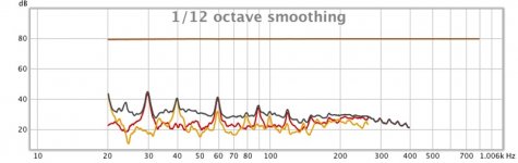
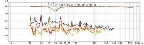
The first chart shows the signal to the speaker. Pretty flat considering it is a quite low voltage signal after passing through a gazillion junctions, a Behringer DSP, a 1975 JVC receiver I bought at the Salvation Army for $20 and other digital boxes between John Mulcahy's house and this picture*. Distortion, noise, and hum with my long alligator clips and going back over those gazillion junctions clocks in around 55 dB, as shown by the THD black trace. The other traces are 2nd and 4rd harmonic.
The second chart shows the signal at the top end of the 2.2 Ohm series resistor. Since the driver is adding its own personality and fluctuating back-EMF (fluctuating due to distortion), that is reflected in the voltage across the resistor. THD is a lot more, maybe like -30dB, but I don't know what that really means quantitatively or in terms of what could be accomplished with MF.
The third chart compares the two runs and shows where MF would be applied if you used this crude method. Where the resistor signal is low (because the excessive/distorted moving driver grabs more voltage to itself), you would be cutting the signal to the speaker. For example, at 50 Hz where the speaker resonance is too loud. Where the driver is balking (like the band below resonance), you'd add more power (without MF, you'd be fooling with EQ, a very blunt tool in real-world rooms).
At the right end, you can see the driver's inductance is adding to its impedance and so the voltage across the resistor is lower. You wouldn't be compensating for that in any simple way, but I'm just illustrating the point for readers.
Yup, simple as that.
Using a Wheatstone Bridge instead of a simple series resistor would magnify the sensitivity of the sensor but then you'd have circuit grounding issues to fuss with and still have various-sized shortcomings of VC MF.
Ben
*with a proper shielded test set-up, the THD generally achieves better than 80 dB (.01%)
Attachments
Last edited:
Sorry: make that 2nd and 3rd harmonic.The other traces are 2nd and 4rd harmonic.
B.
Ben,Here we go, using 2.2 Ohm resistor connected to a 15-inch, 8 Ohm driver in a 6 cu ft sealed box.
The first chart shows the signal to the speaker. Pretty flat considering it is a quite low voltage signal after passing through a gazillion junctions...Distortion, noise, and hum with my long alligator clips and going back over those gazillion junctions clocks in around 55 dB, as shown by the THD black trace. The other traces are 2nd and 4rd harmonic.
*with a proper shielded test set-up, the THD generally achieves better than 80 dB (.01%)
*Considering you want to test THD hopefully less than the 10% a typical good driver exhibits at Xmax, you will need a bit of work on the 25% discrepancy between 55 and 80 dB. If you wrap your alligator clip leads into twisted pairs, they will cancel out most of the usual household noise.
In audio "hi-fi" circles, none of your charts look "pretty flat", which would generally be considered within +/- 3 dB.
What does the SPL measure when distortion, noise, and hum clocks in around 55 dB below it?
Good luck,
Have fun!
Art
The purpose for posting the charts was to encourage other people to discover the errors and the error signals lurking in their speakers. For basic series resistor or Wheatstone Bridge VC feedback, you'd likely not want more than .5 Ohm sitting there.Ben,
*Considering you want to test THD hopefully less than the 10% a typical good driver exhibits at Xmax, you will need a bit of work on the 25% discrepancy between 55 and 80 dB. If you wrap your alligator clip leads into twisted pairs, they will cancel out most of the usual household noise.
In audio "hi-fi" circles, none of your charts look "pretty flat", which would generally be considered within +/- 3 dB.
What does the SPL measure when distortion, noise, and hum clocks in around 55 dB below it?
Good luck,
Have fun!
Art
There's no reason to be interested in performance or performance improvement at Xmax. That's where MFB goes into self-destruct mode. The particular charts I posted are at ordinary listening levels or about 110 dB-flat at the grill cloth, with Dayton IMM* mic just at the edge of its linear capacity. Many a DIYer has been led astray by worrying about unrealistic max values at the design stage.
I note your well-intentioned advice about shielding my leads even if you don't understand that it wouldn't matter much with a minuscule 2 Ohm load.
Ben
*very conveniently, the "headphone jack" on some Mac laptops (such as the Air I use for my music server) takes a trick 4 wire plug and so works directly with the IMM USB mic.
Ben,I note your well-intentioned advice about shielding my leads even if you don't understand that it wouldn't matter much with a minuscule 2 Ohm load.
*very conveniently, the "headphone jack" on some Mac laptops (such as the Air I use for my music server) takes a trick 4 wire plug and so works directly with the IMM USB mic.
I have been using the mic in and line out on my Mac Laptop and desktop units for dual FFT testing for 10 years or so, got tired of lugging a large USB mixer around when a simple analog in/out adapter box worked fine. The impedance of the load has no bearing whatsoever regarding SN ratios, the SN of the mic pre-amp "is what it is", in addition to upsteam noise it captures and amplifies.
The "output resistance" you may have measured at 2 ohms is simply a series resistor in curcit to prevent the headphone amp from being shorted while plugging in whatever you decide to plug in to the hole, headphones, adapters, paper clips, screws or what have you .
Shielded twisted pair can get another dB or so SN over a balanced twisted pair, but I was suggesting a "free" fix, knowing your adversity to spending any $$ you can avoid.
My advice did not include shielding, it suggested twisted pair wire, which increases CMR (common mode noise regection) of the usual RF and 60Hz (and harmonics) mains "hum" far more than shielding.
For shielding to be effective for both RF and mains noise, MU metal, as used in the shielding cases on expensive audio in/out transformers, must be used, but effective design and placement proximity has largely eliminated the need for MU metal other than RF prone locations. Examples still requiring MU metal would be radio station studios with their sloppy broadcast antenna located on their roof, or sound studios located in close proximity to the "line of fire" of megawatt RF transmitters.
Getting SN to approach 80 to 100 dB in those situations is a challenge, while in typical homes, not difficult if you attend to some basics, and keep the exposed high gain portions balanced lines.
Cheers,
Art
Last edited:
I see your point as to why rising rate suspensions can be useful in some situations.Continuing with my defense of "stiff" drivers …
By a bit, I meant an amount. Usually I would see increases in the 1.5x to 2x range.Doesn't your use of "a bit" really mean "...distortion might deteriorate a little at some odd frequency or two", rather than "...VC MFB makes distortion a little worse across the band"?
The deterioration is not at odd frequencies, but across the whole 30Hz – 100Hz bass range.
I’ll see if I can dig up one of my old trend measurements…or better yet, you could measure that Brutus woofer of yours.
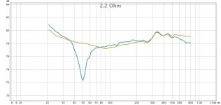
The signal you have plotted is proportional to the current thru the VC. If you measured the impedance, and then calculated the current for a given voltage input and multiplied by the value of your resistor, you would get this curve. Note that it is flat below resonance, where the sealed box woofer response is falling -12dB/oct. So, as I mentioned previously, if you try to use this as a MFB signal you will not flatten this falling response.… using 2.2 Ohm resistor connected to a 15-inch, 8 Ohm driver in a 6 cu ft sealed box….The second chart shows the signal at the top end of the 2.2 Ohm series resistor. Since the driver is adding its own personality and fluctuating back-EMF (fluctuating due to distortion), that is reflected in the voltage across the resistor.
BTW, what woofer is that? If your measurement is correct, it could not be the Brutus 15.
With the dip in the current being only ~7dB the impedance peak would at most be 2x to 3x of Re.
This indicates a pretty weak motor with Qe likely over 2.0.
The Brutus 15 should have close to a 20dB notch in its current signal measurement.
As mentioned above, the signal at the top end of your series resistor is just showing you the current thru your voice coil. Rather than calculating it as applied voltage divided by impedance, you could calculate it as (applied voltage – back EMF) / (blocked impedance) and get the same answer. What is useful for MFB is the back EMF voltage since it is proportional to cone motion (ie velocity). The bridge arrangement does not “magnify the sensitivity of the sensor”. Rather, it enables you to extract that portion of the signal you are interested in (ie back EMF) from the total voltage measured at the sense resistor.Using a Wheatstone Bridge instead of a simple series resistor would magnify the sensitivity of the sensor but then you'd have circuit grounding issues to fuss with and still have various-sized shortcomings of VC MF.
I can post some example plots illustrating this if it would be of help.
Attachments
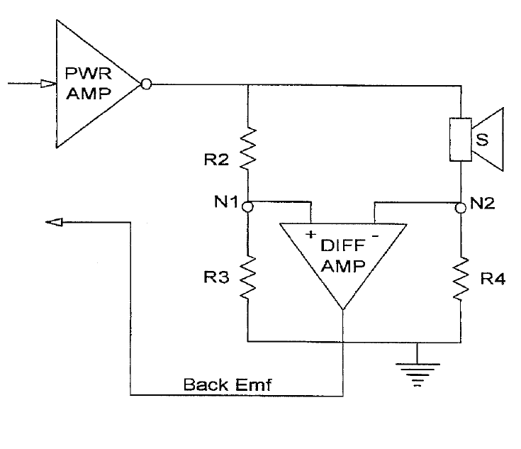
A great difficulty is the presence of a not-EMF signal from the extracted voltage, that is what is due to the part of the impedance of the driver which is not related to the movement of the voice coil in the gap. It needs compensation which can only be very approximative because the voice coil presents :
- a value of inductance which is variable with the frequency and with its position in the gap
- a value of resistance which is variable with frequency, increasing at high frequencies.
These facts seems to have limited the amount of feedback which can be applied to the Wheatstone based servo-systems to 12 dB.
My experience concerning the need for impedance compensation is in complete agreement with your statements.
I was ignoring the complications in the previous post to try and more clearly show how/why the back-emf signal is extracted with the bridge circuit.
Not sure if you saw the measurements I posted showing the effects of ignoring compensation and VC heating.
See attachments and last paragraph of Post#209.
The other thing shown in Post#209 that initially surprised me was that the uncompensated bridge signal matches the signal from the second VC of a DVC woofer. In that case, corruption of the back-emf signal is coming from mutual coupling between the driven VC and the signal VC. Once you draw out the equivalent circuits for each, you can see why this is so.
Since compensation is a compromise at best which eats into phase/gain margin and limits usable loop gain, I found it best to use only woofers for which the need for compensation is pushed above the desired upper bandwidth of the woofer.
- Home
- Loudspeakers
- Subwoofers
- Commercial motional feedback woofer available sort of