beta version (almost?) finished
Hi All
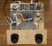
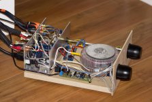
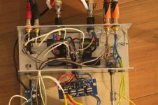
With the remote controlled volume pot in place I would say my first gainclone and first diy project is finished in its beta form. Not the cleanest build I've seen on this forum, but it is working, and already sounding great!
What needs to be added to this beta version:
* led lights to show which source is connected
* led light to show amp is on
* a remote controlled mute relay
The first two might be skipped till the final version, the third I would like to start on now, but to be honest, I have no clue how to do that, even after reading the manual for the remote controlled volume board. The board has the possibility to control a mute relay, but how to build that... No clue. Advice would be highly appreciated.
The final version is going to have some changes compared to the beta:
* volume pot closer to amp boards (could not get that done this time without seriously changing internal lay-out, that's why we make test versions, right?)
* internal power supply for remote board
* cardas patented binding posts
* cardas cinch in- and outputs
* higher quality and mostly non shielded cables.
* two extra inputs
* decent case
Am I forgetting something?
Last item on my list is a DAC. To be honest, I would just use it to connect my television optical out to the amp (and in the proces, my xbox / media streamer). Is it worth for that purpose to go for Peter's high quality DAC or would something like a maybe slightly modified hong kong DAC be sufficient?
Thanks for earlier input and inspiration for this great new hobby!
Erik
Hi All
With the remote controlled volume pot in place I would say my first gainclone and first diy project is finished in its beta form. Not the cleanest build I've seen on this forum, but it is working, and already sounding great!
What needs to be added to this beta version:
* led lights to show which source is connected
* led light to show amp is on
* a remote controlled mute relay
The first two might be skipped till the final version, the third I would like to start on now, but to be honest, I have no clue how to do that, even after reading the manual for the remote controlled volume board. The board has the possibility to control a mute relay, but how to build that... No clue. Advice would be highly appreciated.
The final version is going to have some changes compared to the beta:
* volume pot closer to amp boards (could not get that done this time without seriously changing internal lay-out, that's why we make test versions, right?)
* internal power supply for remote board
* cardas patented binding posts
* cardas cinch in- and outputs
* higher quality and mostly non shielded cables.
* two extra inputs
* decent case
Am I forgetting something?
Last item on my list is a DAC. To be honest, I would just use it to connect my television optical out to the amp (and in the proces, my xbox / media streamer). Is it worth for that purpose to go for Peter's high quality DAC or would something like a maybe slightly modified hong kong DAC be sufficient?
Thanks for earlier input and inspiration for this great new hobby!
Erik
Attachments
Here are just few example that came up through Google search:
Battery charger
12 Volt Gel Cell Charger
12 Volt Car Battery Charger Circuit Schematic Circuit Diagram
Battery charger
12 Volt Gel Cell Charger
12 Volt Car Battery Charger Circuit Schematic Circuit Diagram
hi, i'm building LM3875 kit bought from audiosector last year..and i have a question
can i use center tapped transformer with the LM3875 PSU board? i know it requires dual secondary, but i have 1 center tapped transformer lying around, and if it can be used, why not?
i found this in a website but i want to know more input from other members here..thanx!
link: Power Supply for Power Amplifiers
I've recently built a custom headphone amp based on LM3875 kit. The requirement was to have it fully balanced, preferably in dual mono configuration.
I used one of the custom toroids from toroidy.pl with amorphous core and 4 sets of secondaries at 22V AC ea. The power supplies are located on both sides and 2 LM3875 premium kits have been used in balanced configuration. I didn't do any changes to the kits with exception of replacing 680R resistors with 1k2 to lower the gain. Output is taken directly from between 2 amps.
Initially, we were using Noble pot, each deck across two phases of balanced signal, and it worked quite good, but later at customer request I changed it to Khozmo.
The preamp can handle only balanced sources and there are two sets of outputs, no speaker connection possible. The Integrated Amp chassis, with slight modifications worked very well here.
i'm interested in making gainclone for headphone amplifier. peter, what dc offset reading you got in that amp?
i looked in your manual, dc offset in your kit is pretty high for headphone..around 50mV
any tips to get less than 20mV dc offset without installing input capacitor?
It's a balanced amp so it's relatively easy to sort the chips to achieve 0V differential offset.
The offset from a single chip will depend on a chip itself and also on shunt resistance at the input, see link, where I measure batch of chip at two input impedances (0R and 18K): http://www.diyaudio.com/forums/audi...-kit-building-instructions-5.html#post1524877
The average spread is -25 to 60mV so at certain specific impedance the offset will be 0V.
Input capacitor does not actually reduce offset from a chip, it will only block offset from a source. Using coupling cap will generally increase the offset, as now the usually low source resistance is not in parallel with input shunt resistor of the chip.
Converting bridges for CT transformer application was explained here: http://www.diyaudio.com/forums/chip...oid-wiring-peter-daniels-kit.html#post1196283
The offset from a single chip will depend on a chip itself and also on shunt resistance at the input, see link, where I measure batch of chip at two input impedances (0R and 18K): http://www.diyaudio.com/forums/audi...-kit-building-instructions-5.html#post1524877
The average spread is -25 to 60mV so at certain specific impedance the offset will be 0V.
Input capacitor does not actually reduce offset from a chip, it will only block offset from a source. Using coupling cap will generally increase the offset, as now the usually low source resistance is not in parallel with input shunt resistor of the chip.
can i use center tapped transformer with the LM3875 PSU board? i know it requires dual secondary, but i have 1 center tapped transformer lying around, and if it can be used, why not?
Converting bridges for CT transformer application was explained here: http://www.diyaudio.com/forums/chip...oid-wiring-peter-daniels-kit.html#post1196283
It's a balanced amp so it's relatively easy to sort the chips to achieve 0V differential offset.
The offset from a single chip will depend on a chip itself and also on shunt resistance at the input, see link, where I measure batch of chip at two input impedances (0R and 18K): http://www.diyaudio.com/forums/audi...-kit-building-instructions-5.html#post1524877
The average spread is -25 to 60mV so at certain specific impedance the offset will be 0V.
Input capacitor does not actually reduce offset from a chip, it will only block offset from a source. Using coupling cap will generally increase the offset, as now the usually low source resistance is not in parallel with input shunt resistor of the chip.
Converting bridges for CT transformer application was explained here: http://www.diyaudio.com/forums/chip...oid-wiring-peter-daniels-kit.html#post1196283
thanx for the reply, daniel!
i bought the LM3875 classic kit from you last year..did you measure each chip in the package to qualify within several requirement or you just throw any LM3875 chip?
since i'm going to use this amp with my headphone, i really hope the dc offset would be low (<20mV)
as for converting CT trafo to dual secondary..can't i just make 2 ends for the positive wire and 2 ends for the negative, then connect the CT wire to ground? that way i can still use 8 diodes in the PCB. i think using separated regulated PSU for each channel is better, isn't it (4 diodes/channel)?
Last edited:
i bought the LM3875 classic kit from you last year..did you measure each chip in the package to qualify within several requirement or you just throw any LM3875 chip?
since i'm going to use this amp with my headphone, i really hope the dc offset would be low (<20mV)
as for converting CT trafo to dual secondary..can't i just make 2 ends for the positive wire and 2 ends for the negative, then connect the CT wire to ground? that way i can still use 8 diodes in the PCB. i think using separated regulated PSU for each channel is better, isn't it (4 diodes/channel)?
I don't always measure chips and usually Premium kits get lower offset chips than Classic. If someone needs low offset grade, it needs to specified when ordering and even then, it still depends on what I have available.
With a CT transformer, you can only use 4 diodes for symmetrical supply.
As to separate supplies for each channel, it was discussed here: http://www.diyaudio.com/forums/audi...-kit-building-instructions-4.html#post1517735
Hi Peter,
I finished a PS board and 2 mainboards last weekend.
However, when I tried a test-run on PS board, I got a "bang" and all blew up. Here is what happened.
I soldered the PS board with 8 MUR860 following your instruction without 2 caps. I used a RED led with 10k series resistor (should be 62k as you suggested but I tried 10k with this LED with DC PS maximum 30V fine then I think it would be the same with rectifier board).
I used brand-new toroid transformer 300VA 2x25V. Carefully measured the 2 outputs of secondary, I got 27.5V.
Connected the sec. outputs to the PS and turned the power up. BANG. Even the house main breaker shut down. That BANG also broke the fuse of the extension power cord.
Then I checked the toroid, seems OK.
Check the LED, still OK as it can light up.
Check all MUR860 on board, they were broken through, I think because I measured the resistance value between two legs in forward bias and reverse bias, the values are not as usual (usually 1 direction with OL value and the other with some Ohm). further, I think the rectifier board got problem or at least on MUR860 was bad before being soldered (!) as there was no voltage to the LED (because the LED is still ok after BANG).
I haven't tested the PS board with power again after that. I don't have variac as well.
By the way, when I asked my brother who is in electronic, he told me that would be a problem because I did not solder wires from toroid to the PS board. I just let those wires went through the holes with purpose of testing. Obviously they were not very well connected.
What is the actual problem to me? Please help.
I still have another set of 8 MUR860 and a PS board. But I need to clarify the problem before continuing.
Thanks in advance
Regards,
HT
in that it prevents blow ups when the wiring is wrong and reduces the risk to almost nil of the builder being injured due to that error.but don't think it is critical.
It even saves the fuse from blowing !!!!
What is the actual problem to me? Please help.
I still have another set of 8 MUR860 and a PS board. But I need to clarify the problem before continuing.
The only problem I can think of is that the diodes were installed the other way.
If it's PS from LM3875 kit, the diodes should be installed according to picture here: http://www.diyaudio.com/forums/atta...ainclone-kit-building-instructions-diodes.jpg with white stripe marking metal tab orientation. With LM4780 the diodes install the opposite way, but again, white stripes still indicate the correct position.
Not soldering the wires from transformer secondaries shouldn't be a problem, also mixing them wouldn't be a problem either as both rail circuits are completely separate on this PS board.
The LED should not affect anything either, with proper resistor (62K is what I use) it's either lights up when installed correctly, or not when placed wrong way.
I do remember reading about the main light bulb tester in Peter's instruction and some posts of this thread but don't think it is critical.
It is indeed not critical, because if everything is assembled carefully without any mistakes, the circuit will work right from a start. The bulb is only needed when you leave chance to errors and need prevention mechanism.
The bulb is certainly critical when developing new circuits, as you never know what may happen.
John Curl uses one too: http://www.diyaudio.com/forums/powe...-surge-problem-toroid-help-2.html#post2242788
The only problem I can think of is that the diodes were installed the other way.
If it's PS from LM3875 kit, the diodes should be installed according to picture here: http://www.diyaudio.com/forums/atta...ainclone-kit-building-instructions-diodes.jpg with white stripe marking metal tab orientation. With LM4780 the diodes install the opposite way, but again, white stripes still indicate the correct position.
Not soldering the wires from transformer secondaries shouldn't be a problem, also mixing them wouldn't be a problem either as both rail circuits are completely separate on this PS board.
The LED should not affect anything either, with proper resistor (62K is what I use) it's either lights up when installed correctly, or not when placed wrong way.
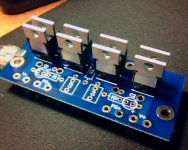
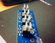
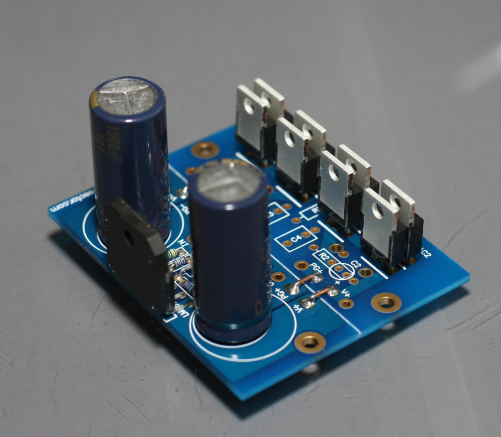
I just managed to have PS' pics from my webcam. It's PS from LM3875 premium kit.
I tested all diodes on board just now using Fluke 179. All are in good condition. Have no idea. May be the PS board is till in good condition.
How do I test the rectifier board without power?
Attachments
Hi DeepBlue.
As PD says, are all the diodes soldered the way you show in your picture.
Solder the Trafo wires to the board. Don't just stick them in as you did. That could be the problem. Tripping your mains , means you had a short circuit. A 300VA trafo would not overload your system.
AS Andrew suggested, the light bulb tester is the safest way.
It is indeed not critical, because if everything is assembled carefully without any mistakes, the circuit will work right from a start. The bulb is only needed when you leave chance to errors and need prevention mechanism.
The bulb is certainly critical when developing new circuits, as you never know what may happen.
John Curl uses one too: http://www.diyaudio.com/forums/powe...-surge-problem-toroid-help-2.html#post2242788
I didn't use bulb-method.
I just remembered that I bought an AC-AC adapter (230V-100mA to 9V-200mA). This was my mistake to buy it instead of AC-DC
 but now it become useful . I used this AC-AC adapter to test the PS.
To my surprise, the PSI works. The adapter output is 11.13VAC and PG+-V+ is 9.88VDC and PG--V- is 9.63VDC.
Then I tried this adapter output to the toroid's pri. The toroid's sec is 1.29VAC. And the PSI output is 0.96VDC and 0.94VDC arcordingly.
Happy! But I wonder the values are ok?
It's 1:00am now. I will test the PSI with main power (230VAC) + toroid tomorrow.
But I still doubt what made BANG with small "thunder" yesterday??? BTW, I still have not found bulb tester diagram. I will find the instruction to make it for my own use.
Thanks everyone for suggestions, references and advices!
HT
- Home
- More Vendors...
- Audio Sector
- Commercial Gainclone kit- building instructions