I have not paid it yet, so I can return it. Should I return it and get a 300VA or there will be no difference?
There won't be any difference
ok i tried adding a RC snubber (100ohm, .10uf) across the switch and it is keeping the amp on all the time.Place a small Class X1 rated capacitor (around 0.1 uF /275 volts is fine) across the switch contacts. This will help protect the contacts from arcing and also stop them from making a noise when the switch is operated.
as said before i have it across the switch at the moment but it's keeping it on all the time.Try adding a snubber across the transformer primary, not across the switch.
They make snubbers that integrate a resistor and capacitor inside the one case specially for this.
is what you are saying is add it to the + and - of the power plug?
i think i measured the resistince of everything and it came out to like 3-5ohms. that is going threw the switch and threw the transformer.
No, not across the power plug, not across the switch.ok i tried adding a RC snubber (100ohm, .10uf) across the switch and it is keeping the amp on all the time.
as said before i have it across the switch at the moment but it's keeping it on all the time.
is what you are saying is add it to the + and - of the power plug?...............
Try adding a snubber across the transformer primary,
Any advice on positioning the different parts in the box? Eg should some cables be as short as possible? Should some parts/cables be not close to some others? Is symmetry important?
I intend to make a stereo amp with 1 transformer and a volume pot all in one box, which I will buy when I know how I position everything.
Thank you!
I intend to make a stereo amp with 1 transformer and a volume pot all in one box, which I will buy when I know how I position everything.
Thank you!
Here's a good example how to position everything: DIY Chip Amplifier Kits, PCB's, Components and Information.
Generally, input signal wires should be as short as possible; instead of running wires from inputs to source selector/attenuator back to front, it's better to use shaft extenders on those controls.
Transformer can be close to amp circuitry, I never noticed any problems with that.
Symmetry is not critical.
well here's more pic's. going to use some thermal epoxi to "glue" the lm3875 to the heatsink instead of the thermal tape. tape just wasn't secure enough and i dont want to drill and tap to mount them. also going to try to add a cap accross the power button to help it not spark as much. other then that she's done.
You are using some weired technology in that amp. A power switch should not spark in a circuit like this. Can you post a link to that part and how exactly is it wired?
You are using some weired technology in that amp. A power switch should not spark in a circuit like this. Can you post a link to that part and how exactly is it wired?
not really anything different then what your kit is. only thing that would be different would be the buck converter that is attached where the led light goes on the power board to go from 32v to 2.4v ish so it lights up the led on the switch and not burn it out.
the switch i am using is a e-switch ULV4F23SS331
https://www.e-switch.com/product-ca...ies-anti-vandal-switch-ul-listed#.Vr4xjyArJD8
its wired so that the positive comes from the power plug (fused) to the C on the switch and the transformer is on the NO or the switch. when switch is activated it switches from the NC to the NO and it sparks a little on the inside. the other tabs are just for the led ring that lights up on the out side.
They specificaly say that the adhesive "is NOT intended to be used between a CPU and the CPU heatsink", so how you use it with a tape?
heh im not using both at the same time just one at a time. the don't use for cpu heatsink is because its a permanent bond and wouldn't allow for cpu removal if needed.
Arcing inside the switch is most likely cased by inrush of transformer current.
You may check this thread for more info: http://www.diyaudio.com/forums/power-supplies/204603-arcing-mains-switch-add-cap-parallel-why.html
You may check this thread for more info: http://www.diyaudio.com/forums/power-supplies/204603-arcing-mains-switch-add-cap-parallel-why.html
Hi, I'm hoping someone can point out where I went wrong with this wiring saving me from potentially a lot of rework. I'll include some pics here as well.
Psu is an Antek 300VA 22V dual secondaries and I've followed the instructions for a stereo configuration with volume pot (10k valab stepped attenuator in my case ) mostly up until having issues with hum but no music.
I've tested the rectifier output before connecting the amps to be 33.8 and 33.5 and the led works.
Now when checking for DC offset I suspected something wrong as outputs on were showing 40.3 mvac left and 21 on the right while in vdc I'm getting 29.4 and -29.8 respectively.
I'm thinking of rewiring the star grounding scheme but can't help thinking something else is wrong.
Attachments
Wow, that was easy! You saved me a lot of time and I can't thank you enough for pointing out the missing Rf on the amps. It's sounds great, no hum at all just the music through a pair of sacrificial jvc speakers I found at our dumpster for this purpose.
I'm thinking the valab 10k 23 stepped attenuator may need to be swapped for a 25 or 50k though since it's pretty quiet throughout it's range up until max volume where I just leave it and adjust with the source.
Now I can move forward with finishing it off.
Thanks again Mark!
I'm thinking the valab 10k 23 stepped attenuator may need to be swapped for a 25 or 50k though since it's pretty quiet throughout it's range up until max volume where I just leave it and adjust with the source.
Now I can move forward with finishing it off.
Thanks again Mark!
Almost there
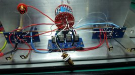
Hi, Ive been dragging this out for a long time, I am now almost ready to fire this thing up. Ive got a quick grounding question, i havnt put the chassis earth on the amps yet but its regarding input ground to the boards. Its going to be a single input system for now, this will feed my LDR which has one tiny screw clamp for a common return so i have joined them together as you can see at the top of the pic. Thats all fine, the rca's at the bottom are outputs to my plate amps, as with the ldr the DCB1 only has one common input/output return and I am splitting the signal to the 3875's. My plan is to run the DCB1 3 output wires to the lower RCA's then run links to the GC's, so SG for both boards will be soldered to that copper link between the output RCA's. I dont see any other sensible way to do it and at the end of the day the returns always meet up somewhere but I thought it worth asking in case Im doing something that will result in noise, I could just suck it and see but I will sleep better asking the question first.
![URL]](/community/proxy.php?image=http%3A%2F%2F%5BURL%3Dhttp%3A%2F%2Fs741.photobucket.com%2Fuser%2FDawgno1%2Fmedia%2FGC%2FGC.jpg.html%5D%5BIMGDEAD%5Dhttps%3A%2F%2Fi741.photobucket.com%2Falbums%2Fxx59%2FDawgno1%2FGC%2FGC.jpg%5B%2FIMGDEAD%5D%5B%2FURL%5D&hash=b4bacf9b49551ca00d9b391fabe4babf)
Hi, Ive been dragging this out for a long time,
I am now almost ready to fire this thing up. Ive got a quick grounding question, i havnt put the chassis earth on the amps yet but its regarding input ground to the boards. Its going to be a single input system for now, this will feed my LDR which has one tiny screw clamp for a common return so i have joined them together as you can see at the top of the pic. Thats all fine, the rca's at the bottom are outputs to my plate amps, as with the ldr the DCB1 only has one common input/output return and I am splitting the signal to the 3875's. My plan is to run the DCB1 3 output wires to the lower RCA's then run links to the GC's, so SG for both boards will be soldered to that copper link between the output RCA's. I dont see any other sensible way to do it and at the end of the day the returns always meet up somewhere but I thought it worth asking in case Im doing something that will result in noise, I could just suck it and see but I will sleep better asking the question first.
Hi, Ive been dragging this out for a long time,
The only sensible reply I can give you is that we will sleep better if you first do it and then ask questions
")
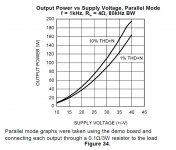
In cases like that it's alwyas best to check datasheet. Page 14 shows a following graph; such transformer is acceptable and you'll be getting approx 140W with parallel config into 4 ohm load.
Thanks will get some improvement using 2 transformers instead one? i found 2 transfformers with 23-0-23 300VA at home
- Home
- More Vendors...
- Audio Sector
- Commercial Gainclone kit- building instructions