For LM3875 I read in the manual that you use always transformer 300VA for monos or stereo. For stereo some supplier advised me that it would be better instead of 1 300VA to make 2 monos with 2 160VA. What is your opinion about that?
(My speakers are small and the listening distance is small too (about 80cm))
Thank you!
(My speakers are small and the listening distance is small too (about 80cm))
Thank you!
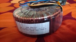
Bigger transformers usually sound better with those kits. I never tried smaller than 220VA and even then the sound seemed a bit "thin".
It will all depend on brand of transformer as well; if you want to go with 2 x 160VA units, choose quality R-core transformers instead of toroids.
It will all depend on brand of transformer as well; if you want to go with 2 x 160VA units, choose quality R-core transformers instead of toroids.
"Pin 1 and 4 on the chip are power pins and they connect to the planes in top layer. Please
make sure that corresponding connection pads have enough solder in top layer as well."
It seems easy to me to solder the front pins on the top side, but things at the back pins are quite narrow, how can be solder applied on the top side?
Thank you
make sure that corresponding connection pads have enough solder in top layer as well."
It seems easy to me to solder the front pins on the top side, but things at the back pins are quite narrow, how can be solder applied on the top side?
Thank you
Soldering info on first page: http://www.diyaudio.com/forums/audi...ne-kit-building-instructions.html#post1508812
If you have problems with solder flow, use rosin flux: https://www.youtube.com/watch?v=TAQa8hUuL2U
If you have problems with solder flow, use rosin flux: https://www.youtube.com/watch?v=TAQa8hUuL2U
just finished my 2nd gainclone and i have to say it tuned out awesome!! way better then my first one. ill have to get pics later.
one question, is there any way to get rid of a spark when switch is turned on?
i know you use a small high volt dime capacitor but not sure how it is implemented.
one question, is there any way to get rid of a spark when switch is turned on?
i know you use a small high volt dime capacitor but not sure how it is implemented.

Try adding a snubber across the transformer primary, not across the switch.
They make snubbers that integrate a resistor and capacitor inside the one case specially for this.
isn't a RC snubber suppose to go in parallel with the current? also can you guide me to finding the size of a resister i would need? i have a 3w 330ohm here i could use but that may be too high.
@Peter Daniel, do you know where I could buy this kit here in Manitoba?
Only directly from me.
well here's more pic's. going to use some thermal epoxi to "glue" the lm3875 to the heatsink instead of the thermal tape. tape just wasn't secure enough and i dont want to drill and tap to mount them. also going to try to add a cap accross the power button to help it not spark as much. other then that she's done.


the chipamp must be securely fastened and thermally coupled to the heatsink................... going to use some thermal epoxi to "glue" the lm3875 to the heatsink instead of the thermal tape. tape just wasn't secure enough and i dont want to drill and tap to mount them................
Do not use sticky tape.
Bolt, or clamp, it to the heatsink.
the chipamp must be securely fastened and thermally coupled to the heatsink.
Do not use sticky tape.
Bolt, or clamp, it to the heatsink.
im well awar about making sure they stay attached. both ways are thermally coupled just fine and are meant for attaching to heatsinks.
the thermal tape is 8805 from 3m http://multimedia.3m.com/mws/media/...ctive-adhesive-transfer-tapes-8800-series.pdf
and the adhesive is aratic silver alumina Arctic Alumina Thermal Adhesive
- Home
- More Vendors...
- Audio Sector
- Commercial Gainclone kit- building instructions