This was supposed to be a simple symmetric (SimSym) amp but now it's not so simple anymore and with optos etc it will defenately not be simple.
I'll keep the idea with optos in the back of my head maybe for a later project.
Did some final changes (changed 56pF caps to silvered mica ones because the one I had chosen from Elfa isn't beeing stocked anymore).
Right now I got my finger on the order button .
.
I'll keep the idea with optos in the back of my head maybe for a later project.
Did some final changes (changed 56pF caps to silvered mica ones because the one I had chosen from Elfa isn't beeing stocked anymore).
Right now I got my finger on the order button
.
A bridged output?
Any thoughts of added another output pair(s) to make this a bridged output structure and lowering the supply voltage a bit?? Maybe you'd need a total of 16 output devices to cope with the increased current with the somewhat higher voltage output. I guess it wouldn't be a 100W/8 ohm amp any more....much higher I think. And not so simple anymore.
I do love the design. Clean and very straight forward. If I had a need. I'd build it. Thanks for all your work.
Bill
I have thought about adding a second pair of output transistors and also about a version with four output pairs.
Bridging however I haven't thought about and I'm not going to try to bridge anything just yet. This is only my second discrete amplifier so far, well actually it's becoming my first because the first one is no where near ready.
But if this one turns out to work good I might make two more versions of it with two and four output pairs.
Bridging however I haven't thought about and I'm not going to try to bridge anything just yet. This is only my second discrete amplifier so far, well actually it's becoming my first because the first one is no where near ready.
But if this one turns out to work good I might make two more versions of it with two and four output pairs
.a "not simple" opto bias control for mirror loaded symetrical diff pair:
http://www.diyaudio.com/forums/showthread.php?postid=637347#post637347
http://www.diyaudio.com/forums/showthread.php?postid=637347#post637347
Bridging....a correction
You would only need 8 output devices (not 16) to do it right for 8 ohms. I'd use +/-40 volts as the supply and you'd have over 300 watts into 8 ohms easily. You could get by with 4 devices (maybe) but in the real world, 8 ohms ain't 8 ohms at all frequencies.
You would only need 8 output devices (not 16) to do it right for 8 ohms. I'd use +/-40 volts as the supply and you'd have over 300 watts into 8 ohms easily. You could get by with 4 devices (maybe) but in the real world, 8 ohms ain't 8 ohms at all frequencies.
Re: Bridging....a correction
for 300W into 8r0 bridged you need 150W into 4r0 and from +-40Vdc. A 2pair output stage should be sufficient for any severe reactance speaker.
That's a total of 8 devices for a mono channel.
without doing any calculations, I'm inclined to agree.stoc005 said:You would only need 8 output devices (not 16) to do it right for 8 ohms. I'd use +/-40 volts as the supply and you'd have over 300 watts into 8 ohms easily. You could get by with 4 devices (maybe) but in the real world, 8 ohms ain't 8 ohms at all frequencies.
for 300W into 8r0 bridged you need 150W into 4r0 and from +-40Vdc. A 2pair output stage should be sufficient for any severe reactance speaker.
That's a total of 8 devices for a mono channel.
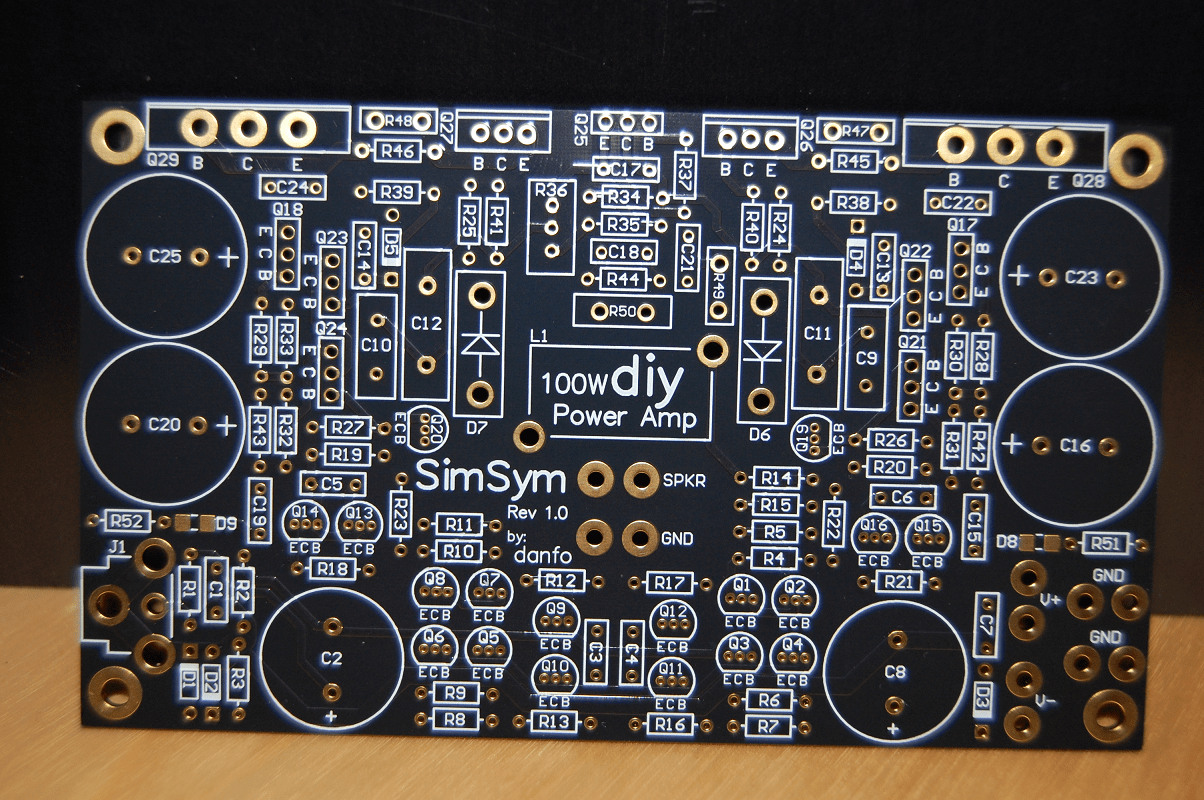
It's been a while but finally I've assembled the amplifier and tested it. And it works! I'm going to have to adjust som values in the vbe multiplier though because the maximum quiescent current I can set is ~37 mA and according to the sim it should be ~80 mA.
I'll post some high res pictures later but for now I made a little video.
YouTube - Testing the SimSym Amplifier
The power dissipated in idle is 12 W according to my bench supplies and my multimeter. That's 120 mA @ 100 V and it gets me a bit worried because the currents just don't add up. According to the sim I should get a total of 76 mA @ 100 V in idle.
But anyway it seems to work fine I've been playing for hours (not very loud though) and no smoke yet.
And excuse the shakyness in the video I've had to much coffe today.
To get the quiescent current I measure the voltage drop over the 0R1 emitter resistors (both at 3.7 mV with R36=0R). To get the total current I've measured the current coming out/in of/to the +-50 V rails with my multimeter in series and the bench supplies also confirms 120 mA.
The bench supplies show 25 V in the video but it's a 2x0-30 V supply with a button to series connect both supplies so it's 2x25 V per supply.
I haven't done any more measurements. The card is so compact and packet with components that it's hard to get access without accidentally shorting something.
I forgot to include the zener current for the cascode biasing so the total should be 81 mA.
I've done some further measurements on the total current consumption and now my multimeter shows 90 mA on both rails (it's a velleman DVM92, I really need to get a better one). I also revisited the simulation and it says 94 mA on the positive rail and 92 mA on the negative rail (with 39 mA quiescent current) so now it seems that all the currents do add up.
However the bench supply still shows 120 mA but I don't trust it.
The dc offset is 2 mV according to the velleman, (simulator says 17 mV).
I've also measured the voltage drop over the 22R filter resistors ~0.9 V and that checks out with the simulator.
Now I need to get a scope and a signal generator to.
Thank you.
The output emitter resistors are caddock MP930 0R1 30 W, and they are mounted on the heatsink.
http://www.caddock.com/Online_catalog/Mrktg_Lit/MP9000_Series.pdf
The output emitter resistors are caddock MP930 0R1 30 W, and they are mounted on the heatsink.
http://www.caddock.com/Online_catalog/Mrktg_Lit/MP9000_Series.pdf
- Status
- This old topic is closed. If you want to reopen this topic, contact a moderator using the "Report Post" button.
- Home
- Amplifiers
- Solid State
- Comments on this symmetric design