Only the Vishey RN60's will be an issue, all others should fit fine.
I couldnt resist so dropped into the office today to pick up my Mouser box!!!
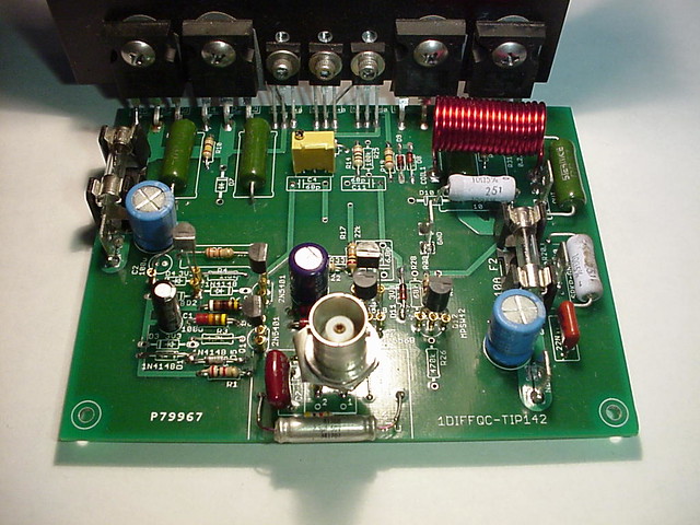
All of my resistors are stuffed and trimmed.")
I always mount resistors 3-5mm off the board as a rule, this seemed to help on this board with the tight spacing. A few parts are on the underside as discussed earlier in the thread.
Back to the bench
I couldnt resist so dropped into the office today to pick up my Mouser box!!!
All of my resistors are stuffed and trimmed.
I always mount resistors 3-5mm off the board as a rule, this seemed to help on this board with the tight spacing. A few parts are on the underside as discussed earlier in the thread.
Back to the bench
WSJ,
I notice that you have the transistors mounted in a small riser. Is this so you can change these for others or am I missing something here? That looks much nicer than soldering them directly to the board. What is the part # for that and where do they come from?
Steven
I notice that you have the transistors mounted in a small riser. Is this so you can change these for others or am I missing something here? That looks much nicer than soldering them directly to the board. What is the part # for that and where do they come from?
Steven
WSJ,
I notice that you have the transistors mounted in a small riser. Is this so you can change these for others or am I missing something here? That looks much nicer than soldering them directly to the board. What is the part # for that and where do they come from?
Steven
Push them out of an IC socket.

http://www.jameco.com/webapp/wcs/stores/servlet/Product_10001_10001_114412_-1
720-AG2D
http://www.aboveboardelectronics.com/thomasandbetts/pdf/au_sockets/dip_700.pdf
http://www.ebay.com/itm/720-AG2D-AUGAT-2-1437542-9-20-Pin-IC-CARRIER-SOCKET-/370297041255?pt=LH_DefaultDomain_0&hash=item56376c7167
Last edited:
Anyone can tell me where the link is to the schematic on this design.
WSJ, Now I need to look at the schematic as I see that in a few places it appears you have left out the components and run a straight piece of wire bypassing some values. I will have to look over the notes very carefully to see where in the schematic those are and what you are leaving out. Are these areas that you plan on making value mods depending on the final results of testing? Just saw that and said to myself, he had to have a good reason to do that.....
WSJ, Now I need to look at the schematic as I see that in a few places it appears you have left out the components and run a straight piece of wire bypassing some values. I will have to look over the notes very carefully to see where in the schematic those are and what you are leaving out. Are these areas that you plan on making value mods depending on the final results of testing? Just saw that and said to myself, he had to have a good reason to do that.....
Anyone can tell me where the link is to the schematic on this design.
WSJ, Now I need to look at the schematic as I see that in a few places it appears you have left out the components and run a straight piece of wire bypassing some values. I will have to look over the notes very carefully to see where in the schematic those are and what you are leaving out. Are these areas that you plan on making value mods depending on the final results of testing? Just saw that and said to myself, he had to have a good reason to do that.....
I was missing the 3 volt zeners, so made a different current source. No need to make any changes, the current source on the original design works fine.
Anyone can tell me where the link is to the schematic on this design.
Hi Steven
Check out post #206
Cheers
Thanks WSJ, you had me thinking I missed something in the conversation and Thanks Dagwood for the post #. I'll print it out and have it on hand. I will have to look at the parts I received and see if I have the same problem with parts type. The resistor misquote was what originally caught me by surprise.
Steven
Steven
Push them out of an IC socket.
You know, that is such an obvious solution to getting stand offs I'm ashamed I didn't think of doing that myself! So ty for the tip.
Has anyone else order straight off the BOM and ended up with TIP142's in the TO-220 package rather than the TO-247 package! infact the BOM lists SOT93 in the package type??
I should have checked the datasheet but luckly RS here in NZ have them in stock.
Thanks Dagwood for pointing out that.
Thank you for being understanding too. Will fix that today. Apologies for the inconvenience.These should do just fine TIP142G ON Semiconductor | TIP142GOS-ND | DigiKey , TIP142 STMicroelectronics | 497-2541-5-ND | DigiKey
Anyone can tell me where the link is to the schematic on this design.
An externally hosted image should be here but it was not working when we last tested it.
Can these amp be bridged? How? and circuit
Hi Vedmitraa, Yes the amplifier can be bridged by
1. Using opamps to invert one input
2. Feeding the output of one to the inverting input of the other
But, load will be limited to 8 Ohms, increase in perceived loudness may not outweigh costs.
- Status
- This old topic is closed. If you want to reopen this topic, contact a moderator using the "Report Post" button.
- Home
- Vendor's Bazaar
- Combined Onaudio thread. (23 threads)