These PCBs can be ready within 5 working days once we select a PCB design. There are PCBs in posts #121, #177, #184. These will require very slight modifications here and there.
However I am still open to suggestions for alternative layouts. We could even have 2 versions.
However I am still open to suggestions for alternative layouts. We could even have 2 versions.
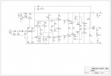
SYMEF (possibly the best amplifier in galaxy) PCB phase 2
After a successful run of 100PCBs. Its time for another run of another 100PCBs. The immediate goal here is to hit the 30,000 PCB mark.
This will be the thread for SYMEF PCB phase 2. Layout contributions are welcome. Show your interest for TO3 or TO264 output devices.
The amplifier thread is here http://www.diyaudio.com/forums/solid-state/198500-symef-amplifier-71.html#post3092022
Last edited:
I have played around with many layouts. Some where perfect in terms of layout logic but were physically challenged (they could make great monoblocks with gigantic cases, but this is diy) . There just has to be that balance. I have to say that the current layout rocks.
On the next run however, I want to experiment. There is a layout that I dreamt up the other day that I want to offer on one of these runs, its a slight deviation from what is on the market in terms of laying out PCBs. I do not know how well it will perform, but it looks very promising.
I will post my ideas and you will post yours. Heres a start.
Attachments
Harrison,
Your layout is actually very favorable for good performance, but I would like to see you decouple the driver side from the power side with a diode per rail and place a few hundred uF for driver reservoir. In my opinion it would be closer to perfection. There is more than enough space on the board for this mod.
Your layout is actually very favorable for good performance, but I would like to see you decouple the driver side from the power side with a diode per rail and place a few hundred uF for driver reservoir. In my opinion it would be closer to perfection. There is more than enough space on the board for this mod.
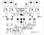
here's my contribution....
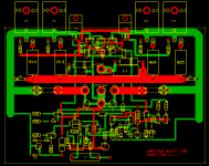
size is 4x3 and decided to separate the zobel and coil section.but I do believe that the amp. should have this, as an external protection for the output transistor.
I have read Jay's post about using rca at input.....and also I have read about balance and unbalanced input.how this small volts rides with the input signal.problem is difficulty employing potentiometer for volume and in case the amp. is still on and plug a device a loud signal will be heard at speaker.
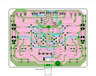
the amp has two gnd returns one is for power gnd and the other is for the signal gnd. going to the star gnd. Signal gnd.is at the top of the pcb which is also the plain gnd. and acts as a shield.
using a star gnd. at pcb is very hard since you have to use a good conductor, very low resistance going to star gnd. otherwise will cause gnd. loop.
my biggest challenge is how to do it in an ordinary two sided pcb.
regards,
drowranger
p.s.
those decoupling capacitors are 33uf for filtering high frequency and having an advantage when decoupling capacitor all having the same value.
size is 4x3 and decided to separate the zobel and coil section.but I do believe that the amp. should have this, as an external protection for the output transistor.
I have read Jay's post about using rca at input.....and also I have read about balance and unbalanced input.how this small volts rides with the input signal.problem is difficulty employing potentiometer for volume and in case the amp. is still on and plug a device a loud signal will be heard at speaker.
the amp has two gnd returns one is for power gnd and the other is for the signal gnd. going to the star gnd. Signal gnd.is at the top of the pcb which is also the plain gnd. and acts as a shield.
using a star gnd. at pcb is very hard since you have to use a good conductor, very low resistance going to star gnd. otherwise will cause gnd. loop.
my biggest challenge is how to do it in an ordinary two sided pcb.
regards,
drowranger
p.s.
those decoupling capacitors are 33uf for filtering high frequency and having an advantage when decoupling capacitor all having the same value.
Attachments
Last edited:
How about adding provisions for 3-4 pairs total of output transistors rather than just two ?
This is something i plan to do, add 1-2 extra pairs of output transistors and bump the 4ohms power up to the 200W mark, and allow 2ohm duty.
Not a bad idea. That can be one version. I am waiting for a few more people to contribute their ideas and layouts. I am waiting for some of the worlds most creative minds to share their ideas. Has something to do with people different perspective of things, if you can harness that, then you can rule the world. Is the glass half full or half empty ?
Thank you drowranger. I know that you are almost ready to build this one and I am very grateful. You will yet again experince the very best the galaxy has to offer.
I would recommend building a full version just like you did the SYMEF. A three layer design like the one you have posted is best implemented at the board house.
Would it be possible for me to entice you with trying out this new layout idea that I am planning to experiment with in the SYMEF.
I would recommend building a full version just like you did the SYMEF. A three layer design like the one you have posted is best implemented at the board house.
Would it be possible for me to entice you with trying out this new layout idea that I am planning to experiment with in the SYMEF.
Attachments
its only two sided..
my gnd. plain is on top and serves also as my signal gnd.power gnd is at the bottom of the pcb.
I have to modify my gnd. plain should not extend to supply section.
my signal and power gnd are not connected so there will be two gnd. returns to star gnd.if this does not work I will try to put a bridge for the two gnd., which is at the top and bottom and there will be one gnd return to star gnd.I hope this will separate the power gnd. and signal gnd. contaminating each other.
Star gnd. should be as close to amp. and maybe use a copper plate as my star gnd. and solder these return wire for good conduction.I have also read about metal enclosure are bad conductors, may be this is the cause when these rca connectors(input connectors) come in contact and produce humming noise..
I dont know if my idea make sense
regards,
joel
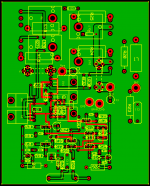
this is my idea...
now I know why you want me to put gnd besides those supply and output tracks.
again this is a two sided pcb composed of two gnd. plain at the bottom(power and signal gnd). with two gnd returns to star gnd.its worth to try experimenting.
regards,
joel
p.s.
forgot the attachments
now I know why you want me to put gnd besides those supply and output tracks.
again this is a two sided pcb composed of two gnd. plain at the bottom(power and signal gnd). with two gnd returns to star gnd.its worth to try experimenting.
regards,
joel
p.s.
forgot the attachments
- Status
- This old topic is closed. If you want to reopen this topic, contact a moderator using the "Report Post" button.
- Home
- Vendor's Bazaar
- Combined Onaudio thread. (23 threads)