Do I understand HornResp nomenclature correctly?
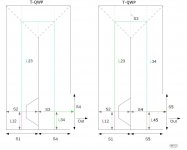
Crude drawing marked up as I understand a 3 section TH in HornResp. Going from the schematic to a "real" enclosure is my goal here. I have question regarding how to best define the distance at the horn fold.
Taking things a bit further:
What would a 4 section TH look like? Almost seems like if I had the port facing down onto the floor , the floor could take on the role as part of the horn, yes/no? S3 would be just above the driver, S4 just below the driver, S5 being the floor. L34 would be the distance between S3 and S4, while L45 would be from S4 to the floor. No sides to the flare on L45, though, that could be a problem.?
Attachments
Hi There: Use S5 as the mouth, S4 where you now have S3 and then S3 can be the missing dimension. If you post the input data, there are members who will run HR and assist you. I ran your otrher posted input data, without Vrc & Lrc, with out problems, result was a strange looking horn with a corresponding strange SPL curve. Don't give up, HR take a lot of work and usually many trials to get decient curves, then you can sweat out folding and how to find room for your drivers! ...regards, Michael
Hi Michael.
IF you are referring to the data set held in "untitled 1.doc", then you betcha! Notice that S2 and S4 are both have a value of 1e-4. Those are not a very big holes! These values came from EasyHorn spreadsheet. I believe the intent is for me to use HornResp's Speaker Wizard to make adjustments to these two values while monitoring the effects of graphs.
Regarding Vrc and Lrc:
What was killing me was not understanding that for a TH neither rear or front chamber volumes are to be considered. Leach's development of his horn equations does consider them, but apparently in the case of a TH, not needed.
I still am agonizing over the affects of the bend at the fold. The opening at the center baffle surely must be a player here, as closing it would not be so good, but I have yet to uncover a "rule of thumb" for sizing that opening. So far I assume to make that area equal to the adjacent duct areas.
I do believe that I am making progress. Things still a bit choppy this early on. Honestly, great fun!
Hi there sdad: Adjust the input data anyway that works for you. I do not bother with the wizzard, just edit the values one at a time and monitor the SPL/watts, speaker Xmax graphs as I go along, with a look at the others along the way. I input the max reasonable Eg (voltage) I intend to use and adjust downward to keep Xmax for the driver in line. Check-out Patric Bateman's referance to EasyTapped Horn (list of 7 instructions) which speeds-up the process. ...regards, Michael
Actually, I do both the wizard and manual entry. I lean toward the wizard in that the primary concerns are grouped quite conveniently, and with an interactive graph while changing parameters is very nice.
Do wish I could get some feedback on that darned area up by the bend, though. ;>)
Do wish I could get some feedback on that darned area up by the bend, though. ;>)
sdad; Start looking here we talked about this quite a bit.Do wish I could get some feedback on that darned area up by the bend, though. ;>)
http://www.diyaudio.com/forums/subwoofers/170771-single-sheet-th-challenge-59.html
...Do wish I could get some feedback on that darned area up by the bend, though. ;>)....
Hi, I recycled your Horn.pdf and drew a new picture:
b
")
Attachments
4pyros: I just breezed over a couple of pages in the thread you pointed out. Thanks. I bookmarked so I can read over entire discussion. A few things popped into my head while passing through. (1) AkAbak has to be learned, and learned well. (2) Would be nice to have an "optimizing" routine that would establish user set boundries for a number of conditions (horn sections, areas, lengths,etc, or in the alternative, spl, impedance,etc) and reiterate through those.
Never satisfied, are we?
Never satisfied, are we?
Bjorno,
post3669 has some of the label in the wrong place.
S4 (left) is not repeated on the blank end.
S5 (right) is not repeated on the blank end.
L34 (left) is not the vertical length to the bottom panel.
L45 (right) is not the vertical length to the bottom panel.
These four labels could only be correct for a TH that has the mouth in the end, not in the side.
Post #3663 and #3665
Hi sdad,
Looks like you're getting it.
As to the a chamber between the driver and the horn throat, see P.19 of the Hornresp help file: "...Vtc and Atc can be used to specify a chamber...Ap1 and Lpt can be used to specify a port..." For a chamber in the other direction, or any other special treatments you need to move on to AkAbak.
As to the distance in your drawing Post #3663, it is just a point in the horn path. You can find any point by exporting the horn data when in the schematic diagram window.
Regards,
Hi sdad,
Looks like you're getting it
.As to the a chamber between the driver and the horn throat, see P.19 of the Hornresp help file: "...Vtc and Atc can be used to specify a chamber...Ap1 and Lpt can be used to specify a port..." For a chamber in the other direction, or any other special treatments you need to move on to AkAbak.
As to the distance in your drawing Post #3663, it is just a point in the horn path. You can find any point by exporting the horn data when in the schematic diagram window.
Regards,
Introduction to active filter in AkAbak
I am somewhat in a spin on incorporating the next step in my TH project. I need to create active filtering, not passive. Looking at the active filter section of the how-to just isn't working for my geriatric brain. I will eventually need to consider LP, BP, and HP filter creation and how to tie the filter to the speaker. Anyone willing to tutor/jump start me? Maybe start off with a LP as a stand alone ckt, a simple resistive load at the output? Then cascade in a HP to form a bandpass?
I will be forever in your debt!!!!!!! Well, maybe not forever
Would someone look this AkAbak script over?
I have attached a script that appears to me as a reasonable first cut. The xmas, group delay seem pretty good. The fr is nice as it doesn't really need to cover much ground. I am after only a single octave here. In fact, I may go after a bit of the high end. I have sufficient floor space so the larger boxes are ok for me. I did leave a "System 'Drvr'" in the script, but it is currently rem'd out. Obviously, remove rem to to see response without the filter.
I have attached a script that appears to me as a reasonable first cut. The xmas, group delay seem pretty good. The fr is nice as it doesn't really need to cover much ground. I am after only a single octave here. In fact, I may go after a bit of the high end. I have sufficient floor space so the larger boxes are ok for me. I did leave a "System 'Drvr'" in the script, but it is currently rem'd out. Obviously, remove rem to to see response without the filter.
Attachments
Look at Horst Moller's double horn designs:
Hornlautsprecher
They are mostly back loaded horns, but they do use the principle of two differently tuned enclosures working together.
Using a common mouth for two tapped horns doesn't save you any space, you still need just as much box volume. And if they are tuned to different ranges and their mouths are close together or common, you will get slightly worse performance because the output of one horn will be partly out of phase with the other horn at some frequencies, causing cancellation.
The only real advantage of having two overlapping passband tapped horns is that if you set the resonant frequencies properly, the electrical impedance peaks can be made to "interleave". This flattens the overall impedance curve seen by the amplifier, which can be useful when using small tube amplifiers etc.
Check out the group delay curve of a tapped horn. You'll see a series of spikes.
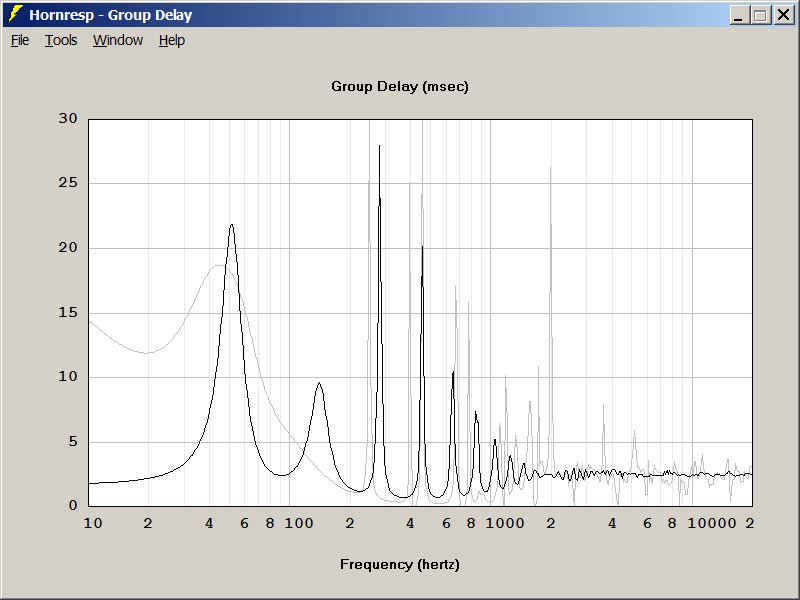
This is a group delay curve for a couple of bandpass designs. (And tapped horns are basically elaborate dual reflex bandpass subs.)
I believe that group delay explains why many people prefer the sound of passive radiators.
What's happening here is that standing waves are created by the horn, and at certain frequencies the group delay curve goes nuts.
One advantage of dual pathlengths is that it reduces the severity of those group delay spikes. We can't eliminate group delay, but staggering the length spreads those spikes out, and reduces their amplitude.
Hope that makes sense.
Read more here:
Audio Psychosis • View topic - [everything you never wanted to know about] Bandpass Boxes
Try this example:
http://www.diyaudio.com/forums/subwoofers/145603-tapped-horn-car-6.html#post1936713
(I think there are some errors in the script provided, though.)
The essential point is to understand that AkAbak allows you to split and merge ducts and waveguides. Remember to match the areas - if you are joining two 100 cm2 mouths to a single throat, the throat has to be 200 cm2.
Here's a basic 4 segment tapped horn schematic using Hornresp-like areas (S1 to S5) and segment lengths(L12 to L45). Exporting a design from Hornresp should produce a similar schematic.
Code:| -------Driver1------- | | | |S1<--L12-->S2<--L23-->S3<--L34-->S4<--L45-->S5-- Radiator
With example AkAbak node numbers added:
Code:| -------Driver1------- | | | |S1<--L12-->S2<--L23-->S3<--L34-->S4<--L45-->S5 |11 12 13 14 15-- Radiator |------------------------------------------------
Define all the horn segments with the "waveguide" element.
(A "Horn" element in AkAbak is a "Waveguide" with a "Radiator" added to its mouth.)
Now add a second horn in parallel:
Code:| -------Driver1------- | | | |S1<--L12-->S2<--L23-->S3<--L34-->S4<--L45-->S5 |11 12 13 14 15-- Radiator1 |------------------------------------------------ |21 22 23 24 24-- Radiator2 |S1<--L12-->S2<--L23-->S3<--L34-->S4<--L45-->S5 | | | | -------Driver2-------
This should generate the same SPL curve, but 6 dB higher in output.
Finally, merge the 2 horns:
Code:| -------Driver1------- | | | |S1<--L12-->S2<--L23-->S3 | |11 12 13 | |----------------------S3<--L34-->S4<--L45-->S5 |21 22 13 14 15-- Radiator |S1<--L12-->S2<--L23-->S3 | | | | | -------Driver2-------
Remember to make S3 (for the L34 segment), S4 and S5 equal to twice the original areas.
The SPL curve should match that for the previous version.
This script simulates the drawing you provided earlier of the two horns oppposite each other with a shared mouth area.
You can now make the lengths of the 2 segments in the "second" horn different from the corresponding sections in the "first" horn.
lol i made that post that you hyperlinked to, and I can't even make heads or tails of it
I know that I've posted an Akabak model for a 2, 3, and 4 woofer tapped horn.
My personal fav is to use two woofers, with one inverted. That reduces 2nd harmonic distortion, and staggering the woofers smooths out the group delay curve and makes the peaks and dips go away for the most part.
I believe this is why Danley uses dual woofers in the TH-Spud, besides the obvious power handling improvements.
...
Check out the group delay curve of a tapped horn. You'll see a series of spikes.
...
How many of those spikes are in the passband?
- Home
- Loudspeakers
- Subwoofers
- Collaborative Tapped horn project