316a said:
Not many , mainly a brand called 'Skytec'........
Anyone have a hornresp screenshot of the 30Hz horn ?
Greets!
Specs? All I have is for a Skytronics 902 series...... I don't use Akabak or Hornresp.......
GM
Hi GM this one didn't seem to enlarge for me:
http://diy.cowanaudio.com/images/akabak.gif
a larger drawing and more labeling might help
FI
http://diy.cowanaudio.com/images/akabak.gif
a larger drawing and more labeling might help
FI
G'day Freddi
Try this one. I didn't realise some people would have trouble reading the original image. I'll link it to a larger version. It's a little hard arranging the content on a web page because everyone has different screen resolutions, and the lowest possible screen resolution needs to be catered for.
Cheers
William Cowan
Attachments
I have read through most of this thread, and searched diligently on the web, and can't find the answer to some of my questions, and I was hoping y'all might be able to help.
If I wanted to build a tapped horn test bed, can I make the horn part with a specific fixed geometry, and then try different driver configurations?
or
Are the horn geometries directly related to the T/S parameters of the driver assembly?
My thought was to build a prototype that I could then try different driver/port configurations, but this would only work if I can build a horn first, and not change it as I change the other stuff.
One of the rules of thumb seems to be to make the length of the horn about the 1/4 wavelength of the FS of the driver. My thought was to build my horn as big as the FS of the lowest driver that I might test
Also is there a reason to (or not to) line the insde of the horn with felt carpet padding to reduce unwanted higher frequencies?
I thought I'd ask for opinions before I waste sawdust.
Paul
A TH is a 1/4 wave horn, and as such, the geometry is not based on driver parameters. The length is based on desired tuning, hence tuning may in fact be lower than driver fs.
You have to decide on the following:
1. Line length
2. Mouth and throat area
3. Driver offset from throat (if any)
A different driver doesn't require a different box. It is not like a vented box where another driver requires a different box volume or tuning point with a closer connection with fs.
This is my understanding of how it works.
Thanks William.
What would be the script for a case with big rectangular cavity?
What would be the script for a case with big rectangular cavity?
An externally hosted image should be here but it was not working when we last tested it.
This looks like an interesting driver
http://www.bkelec.com/HiFi/drive_units/bsb/monolith_du.htm
cheers
316a
http://www.bkelec.com/HiFi/drive_units/bsb/monolith_du.htm
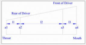
| 30 Hz Tapped Horn with BK Monolith
Def_Const |Horn Dimensions
{
a1 = 315e-4; |Area at throat (cm^2)
a2 = 320e-4; |Area at rear of driver (cm^2)
a3 = 940e-4; |Area at front of driver (cm^2)
a4 = 945e-4; |Area at mouth (cm^2)
l1 = 15e-2; |Distance from throat to rear of driver (cm)
l2 = 350e-2; |Line distance from rear of driver to front of driver (cm)
l3 = 30e-2; |Distance from front of driver to mouth (cm)
}
Def_Driver 'Dr1'
| monolith
Sd=468.7cm2
fs=23.5Hz
Qes=0.416
Qms=2.73
Vas=61.6L
Re=3.7ohm
Le=1.3mH
system 'S1'
Driver Def='Dr1' Node=1=0=3=4
Waveguide 'W1' Node=2=3 STh={a1} SMo={a2} Len={l1} Conical
Waveguide 'W2' Node=3=4 STh={a2} SMo={a3} Len={l2} Conical
Horn 'H1' Node=4 STh={a3} SMo={a4} Len={l3} Conical
cheers
316a
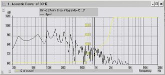
Monolith -= way coll looking driver but looks like 30Hz horn needs to be adjusted
http://img112.imageshack.us/img112/6657/30hzmonolithjk6.gif
http://img112.imageshack.us/img112/6657/30hzmonolithjk6.gif
I´d guess that this doesn´t count as a candidate for TH, since the "horn-part" isn´t really a horn, it´s too short to act as a horn considering the low frequency we are dealing with. More like a tuned enclosure with a widening port and the driver put slightly backwards. Because of the different phase addition there should be an increase in SPL compared to the same box with the driver on the front. The widenig port reacts slightly different then a straight one in a conventional reflex-design, tuning is higher (comparing lenght) and the Q-Factor should also be higher, yealding in a wider response of the port.freddi said:Thanks William.
What would be the script for a case with big rectangular cavity?
An externally hosted image should be here but it was not working when we last tested it.
To verify my assumption, we could throw the design in AKabak and see how it compares to the simulation in AjHorn, which is able to simulate such designs.
I got AjHorn here, so I could try this, but I´d need the impedance of the driver at 1k and 10k, are those available?
Oh, BTW, Thanx very much for all your work on preparing the models!!
While playing around a little and doing some database-search on suitable drivers, I found an older JBL driver (2022H) which seems to have a very nice response down to about 45Hz in a shorter version of the TH-Model.
I looked for drivers with a high fs compared to the acheivable lowest frequency f3, fairly high VAS und high xmax. These seem to be very rare.
I used

look at the range, thats 10dB !
Could someone verify this? I just started to dig my way through in finding suitable drivers and pinpoint the paramters most important.
Another thing I was thinking about: When reading Tom´s papers, low excursion of the cone seems to be one of the bigger benefits of THs. I can´t quite figure out, wether akabak plots +- curves (like most other programs) or is it excursion peak-peak (like LSPCad)?
If it´s p-p, the excursion sure is veeeeeery low")
While playing around a little and doing some database-search on suitable drivers, I found an older JBL driver (2022H) which seems to have a very nice response down to about 45Hz in a shorter version of the TH-Model.
I looked for drivers with a high fs compared to the acheivable lowest frequency f3, fairly high VAS und high xmax. These seem to be very rare.
I used
which gives me this:| 50 Hz Tapped Horn with JBL 2022H
Def_Const |Horn Dimensions
{
a1 = 315e-4; |Area at throat (cm^2)
a2 = 320e-4; |Area at rear of driver (cm^2)
a3 = 940e-4; |Area at front of driver (cm^2)
a4 = 945e-4; |Area at mouth (cm^2)
l1 = 15e-2; |Distance from throat to rear of driver (cm)
l2 = 175e-2; |Line distance from rear of driver to front of driver (cm)
l3 = 25e-2; |Distance from front of driver to mouth (cm)
}
Def_Driver 'Dr1'
| JBL 2022H
Sd=527cm2
fs=75Hz
Qes=0.44
Qms=4.3
Vas=42L
Re=4.6ohm
Le=0.7mH
system 'S1'
Driver Def='Dr1' Node=1=0=3=4
Waveguide 'W1' Node=2=3 STh={a1} SMo={a2} Len={l1} Conical
Waveguide 'W2' Node=3=4 STh={a2} SMo={a3} Len={l2} Conical
Horn 'H1' Node=4 STh={a3} SMo={a4} Len={l3} Conical
look at the range, thats 10dB !
Could someone verify this? I just started to dig my way through in finding suitable drivers and pinpoint the paramters most important.
Another thing I was thinking about: When reading Tom´s papers, low excursion of the cone seems to be one of the bigger benefits of THs. I can´t quite figure out, wether akabak plots +- curves (like most other programs) or is it excursion peak-peak (like LSPCad)?
If it´s p-p, the excursion sure is veeeeeery low
that JBL sure looks smooth - re:excursion - should one close the spl plot before hitting akabak's xmax button? how long might the xmax computation take on an older celeron pc? whats the correct procedure?
what does your 50Hz TH sketch look like? (I don''t see well)
RCF has a 6.5mm xmax 12
http://www.usspeaker.com/rcf - L12P540-1.htm
what does your 50Hz TH sketch look like? (I don''t see well)
RCF has a 6.5mm xmax 12
http://www.usspeaker.com/rcf - L12P540-1.htm
freddi said:that JBL sure looks smooth - re:excursion - should one close the spl plot before hitting akabak's xmax button? how long might the xmax computation take on an older celeron pc? whats the correct procedure?
I guess it´s enough if you focus on the script-window, then hit the xmax-button and calculate. no closing of the SPL window is necessary, AFAIK. At least not here with my version.
Calculation even on an old celeron should only take a few seconds. Akbak was designed a while ago and back then PCs were much slower. On my "ancient" Athlon XP 1,6Ghz, everything pops up immediately
It´s the same concept as the ones before, only a little shorter.what does your 50Hz TH sketch look like? (I don''t see well)
Thanks, I´ll investigate.
Found something on excursion in the manual:
Am I thinking correct?
As far as I understand it, this means the excursion diagramm shows peak-peak values, so a driven given with 4mm +- xmax(lin) should be fine within 8mm shown in Akabak.Diaphragm excursion of Driver, Bassunit, Speaker
Xmax is the maximum amplitude of the diaphragm excursion.
The diaphragms of electroacoustical drivers cannot be moved by any arbitrary amount. In the electrodynamic driver, the diaphragm excursion is provided by, for example, the depth of the magnet gap and the height of the voice-coil development. The half of the difference between these two dimensions is approximately the Xmax of the particular driver. If this excursion is exceed, intense distortions are produced. The list value can be compared with the loudspeaker
data and the maximum input voltage, for example, can be calculated from this.
Am I thinking correct?
I get stuck "here" after minimizing the spl window then hitting xmax button - says "please select item"
http://img238.imageshack.us/img238/466/stucklv8.gif
http://img238.imageshack.us/img238/466/stucklv8.gif
- Home
- Loudspeakers
- Subwoofers
- Collaborative Tapped horn project