Hi Patrick Bateman,
i adapted the script to your application of a TH in a sonotube by changing the waveguides to ducts and implementing a second driver which sits in the horn directly above the first. I cant model a cut in half tube. In the model the tubes on both sides of the driver would be rectangular with each sidelength defined by the variable X. Use the squareroot of the area of your sonotube cut in half as X as an approximation of the real thing.
By the way... in my last post where i included the 55-2421 definition i forgot to change the diameter according to a 8 inch driver (so the sd was of a 12 inch driver). i assume your driver has a sd of about 200cm². the following implementation is correct in this aspect.
Good luck with you project.
Def_Driver '55-2421'
dD=16cm |Piston
fs=29.1Hz Mms=59.78g Qms=14
Bl=12.99Tm Re=3.4ohm Le=2.47mH ExpoLe=0.618
Def_Const | all sizes in centimeters
{
DriverSize = 16e-2; | The outer driver diameter
Hornlength = 335e-2; | The overall length of the horn including the ducts around the driver
X = 12.7e-2; | The length of one side of a rectangular hornpath
Mass = 1.85/X;
}
System 'TH for Dummies'
Driver 'Da' Node=2=0=101=109 Def='55-2421'
Driver 'Db' Node=2=0=102=108 Def='55-2421'
Duct 'D1' Node=101 dD={X} Len={Driversize/2}
Duct 'D2' Node=101=102 WD={X} HD={X} Len={Driversize}
Duct 'D3' Node=102=103 WD={X} HD={X} Len={Driversize/2}
Duct 'D4' Node=103=104 WD={X} HD={X} Len={(Hornlength/2)-DriverSize-Driversize}
AcouMass 'Bend1' Node=104=105 Ma={Mass}
AcouMass 'Bend2' Node=105=106 Ma={Mass}
Duct 'D5' Node=106=107 WD={X} HD={X} Len={(Hornlength/2)-DriverSize-Driversize}
Duct 'D6' Node=107=108 WD={X} HD={X} Len={Driversize/2}
Duct 'D7' Node=108=109 WD={X} HD={X} Len={Driversize}
Duct 'D8' Node=109=110 WD={X} HD={X} Len={Driversize/2}
Radiator 'Rad1' Node=110 Def='D8' WD={X} HD={X}
Thanks for providing your input.
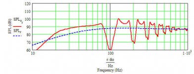
Here's a comparison of your new model, versus the old model.
I used the old model with a single "virtual" driver which encompassed parameters that are equivalent to a pair of MCM 55-2421s. The new model defines the two drivers explicitly.
As the pic here shows, the differences are (fairly) minimal; mostly a bit more output in the midbass.
An externally hosted image should be here but it was not working when we last tested it.
Hey all, since you are all getting into the swing of aKaBak modeling perhaps someone would like to attempt modeling my TH and see if they can get it to match the Measured response of my TH.
The internal width is ~16.5" I originally modeled mine with 18mm birch in mind .709". I built the outside of this proto with 3/4" MDF since its cheap so the Internal Dimensions will be a little off but I'm sure its close enough. All of my internals are made from 18mm Birch ply, since I had enough scrap laying around.
The TS parameters for the kove driver are
dD=27.58cm |Piston
fs=49.7Hz
Mms=120.9g
Cms=0.0000848m/N
Rms=6.309Ns/m
Bl=21.03Tm
Qms=5.986
Qes=.555
Vas=.043m3
Re=6.5ohm
Le=1.595mH
Xmax~18mm
I'll try hacking away and seeing if I can get it right, I thought I was close to dead on until I sealed up the box nice and tight. I was sort of shocked at my response graph afterwards. It was actually better than I predicted. Lifes Happy little accidents.
Antone-
Hi sumsound, i made the akabak layout for your TH. You know the horn better, so it should be easier for you to put the right numbers into it and calculate the acoustic masses between the ducts and for the bends.
The schematic is here:
http://img460.imageshack.us/img460/3414/th2layout1reduxzq8.jpg
Def_Const | all sizes in centimeters
{
Z = e-2; | The height of your box
}
System 'Tapped Horn'
Driver 'D' Node=2=0=100=111 Def='xxx'
Duct 'D1' Node=99 WD= HD={Z} Len=
Duct 'D2' Node=99=100 WD= HD={Z} Len=
AcouMass 'Transition23' Node=100=101 Ma=
Duct 'D3' Node=101=102 WD= HD={Z} Len=
AcouMass 'Transition34' Node=102=103 Ma=
Duct 'D4' Node=103=104 WD= HD={Z} Len=
AcouMass 'M1' Node=104=105 Ma=
AcouMass 'M2' Node=105=106 Ma=
Duct 'D5' Node=106=107 WD= HD={Z} Len=
AcouMass 'Transition56' Node=107=108 Ma=
Duct 'D6' Node=108=109 WD= HD={Z} Len=
AcouMass 'Transition67' Node=109=110 Ma=
Duct 'D7' Node=110=111 WD= HD={Z} Len=
Duct 'D8' Node=111=112 WD= HD={Z} Len=
Radiator 'Rad1' Node=112 WD= HD={Z}
Hehh you missed the first bend and didn't count the transistions as air masses. I know the math is a pain in the ***, though
Thanks I'll show you what I have so far.
I have a parallell path for the rear of the driver, I get radically different response graphs without the Rear path I think by default all of the ducts act unidirectional.
Def_Driver 'Kove'
Meas_DiPole
dD=27.58cm |Piston
fs=49.7Hz
Mms=120.9g
Cms=0.0000848m/N
Rms=6.309Ns/m
Bl=21.03Tm
Qms=5.986
Qes=.555
Vas=.043m3
Re=6.5ohm
Le=1.595mH
ExpoLe=0.618
Def_Const |Global constants
{ z = 25.4e-2; |mouth height
y_f = 32.2e-2; |enclosure depth
y_r = 1.9e-2; |mouth depth
x_fr = 41.9e-2; |enclosures width
x_c = 125.6e-2; |segment height
x_D1 = 12.1e-2; |Position of first driver
x_D2 = 36.3e-2; |Position of second driver
}
System 'S1'
Resistor 'Rg' Node=1=2 R=0.5ohm |Generator resistance
Driver 'Kove' Def='Kove' Node=2=0=100=110
Duct 'Du_F0' Node=100=120
dD=25.4cm Len=1.801cm
Duct 'Du_FX' Node=140=0
dD=12.979cm Len=15.646cm Visc=1
Duct 'Du_F1' Node=130=140
dD=12.979cm Len=15.646cm Visc=1
Duct 'Du_R1' Node=140=130
dD=12.979cm Len=15.646cm Visc=1
Duct 'Du_F2' Node=120=130
dD=12.979cm Len=87.046cm
Duct 'Du_R2' Node=130=120
dD=12.979cm Len=87.046cm
AcouMass 'Ma1' Node=120=150 Ma=25.34kg/m4
AcouMass 'MaR1' Node=150=120 Ma=25.34kg/m4
AcouMass 'Ma2' Node=150=160 Ma=25.34kg/m4
AcouMass 'MaR2' Node=160=150 Ma=25.34kg/m4
Duct 'Du_F3' Node=160=170
dD=17.544cm Len=1.201m
Duct 'Du_R3' Node=170=160
dD=17.544cm Len=1.201m
AcouMass 'Ma3' Node=170=180 Ma=.375667kg/m4
AcouMass 'MaR3' Node=180=170 Ma=.375667kg/m4
Duct 'Du_F4' Node=180=190
dD=25.104cm Len=35.865cm
Duct 'Du_R4' Node=190=180
dD=25.104cm Len=35.865cm
AcouMass 'Ma4' Node=190=200 Ma=.138kg/m4
AcouMass 'MaR4' Node=200=190 Ma=.138kg/m4
Duct 'Du_F5' Node=200=210
dD=30.225cm Len=34.084cm
Duct 'Du_R5' Node=210=200
dD=30.225cm Len=34.084cm
AcouMass 'Ma5' Node=210=220 Ma=8.207kg/m4
AcouMass 'MaR5' Node=220=210 Ma=8.207kg/m4
AcouMass 'Ma6' Node=220=230 Ma=7.851kg/m4
AcouMass 'MaR6' Node=230=220 Ma=7.851kg/m4
Duct 'Du_F6' Node=230=240
dD=31.448cm Len=35.885cm
Duct 'Du_R6' Node=240=230
dD=31.448cm Len=35.885cm
AcouMass 'Ma7' Node=240=250 Ma=.0748kg/m4
AcouMass 'MaR7' Node=250=240 Ma=.0748kg/m4
Duct 'Du_F7' Node=250=260
dD=35.672cm Len=35.885cm
Duct 'Du_R7' Node=260=250
dD=35.672cm Len=35.885cm
AcouMass 'Ma8' Node=260=110 Ma=.0405kg/m4
AcouMass 'MaR8' Node=280=260 Ma=.0405kg/m4
Duct 'Du_FR1' Node=110=270
dD=36.749cm Len=31.293cm
Duct 'Du_RFR1' Node=270=280
dD=36.749cm Len=31.293cm
Duct 'Du_FR2' Node=270=280
Len={x_c - z} WD={x_fr} HD={y_f}
Duct 'Du_RFR2' Node=110=270
Len={x_c - z} WD={x_fr} HD={y_f}
|AcouMass 'Ma9' Node=280=290 Ma=7.834kg/m4
Duct 'Du_FR3' Node=280=290
Len={y_f} WD={x_fr} HD={z}
Duct 'Du_ov' Node=290=300
Len={y_r} WD={x_fr} HD={z}
Radiator 'Rad1' Def='Du_ov' Node=300
x=0 y=0 z=0 HAngle=0 VAngle=0
I have already posted a schematic somewhere back in this thread.
Antone-
Patrick Bateman said:
I used the old model with a single "virtual" driver which encompassed parameters that are equivalent to a pair of MCM 55-2421s. The new model defines the two drivers explicitly.
Greets!
I can only use a lumped driver in MathCad and I'm not sure how big a Sonotube you used, but with a 12" dia. x 72" long one divided in half by a 1/2" thick baffle I get virtually an identical sim in a ~end loaded TL as your dual driver sim, so wondering what the 'tap' is adding?
GM
Attachments
GM said:
... so wondering what the 'tap' is adding?
GM
Not much, it seems
")
If you mean by "tap", that the driver doesnt sit at the end of the line, but rather somewhere in the middle, then one could say, since its only tapped 8 inches the effect has to be to small to see.
I dont know much about TL theory (which might still be exaggerated), so several answers are possible, if the above answer wasnt right.
- The script does something wrong
- Its a case where different names point to the same thing
- Two different things which behave the same
Well, thats just me pondering about stuff i am still learning. If you could help me out here, i would appreciate it.
Apart from that, i am amazed that different simulations in different programs can lead to the same result.
A tapped horn should have a lot more output than a TL. My hornresp sims showed output comparable to a horn. Also if you look at TDs statement about his TH having IIRC 10 db more output than contrabass. Not bad when you consider it's a single 12" driver compared to two 15" drivers. But who am I to talk? You have heard both of them!
Are your akabak models allowing for the path that goes from the mouth reflected back from the throat?
Are your akabak models allowing for the path that goes from the mouth reflected back from the throat?
I'm window-shopping for 10"-12" drivers - how about Mach5's MAW-12? (one consideration is shipping cost to US - wonder how much?)
Mach5 woofer
http://www.mach5audio.com/product_info.php?cPath=48&products_id=41&osCsid=6afc1
Mach5 woofer
http://www.mach5audio.com/product_info.php?cPath=48&products_id=41&osCsid=6afc1
paulspencer said:You have heard both of them!
Me? I've never heard a good subwoofer. I want to, thats the cause i do this right now
I am a dedicated noob.paulspencer said:Are your akabak models allowing for the path that goes from the mouth reflected back from the throat?
If i understand Akabak correctly, they should do that. The waveguides, ducts and acoustic masses have two nodes to connect them to each other and seem to carry sound both ways.
I have two Focal 10K6411 and they model quite well in a Cowan style TH, so i will give this a try for my 20-50hz happiness.
Hi MaVo - 20-50 is really needed with my system too.
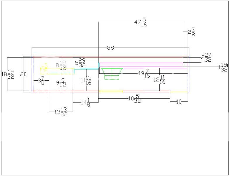
what's needed for script to describe a short tapped-box case which might be useful for DJ/PA work starting with just a baffle holding the driver then adding the panel in red?
what's needed for script to describe a short tapped-box case which might be useful for DJ/PA work starting with just a baffle holding the driver then adding the panel in red?
An externally hosted image should be here but it was not working when we last tested it.
paulspencer said:A tapped horn should have a lot more output than a TL. My hornresp sims showed output comparable to a horn. Also if you look at TDs statement about his TH having IIRC 10 db more output than contrabass. Not bad when you consider it's a single 12" driver compared to two 15" drivers. But who am I to talk? You have heard both of them!
Are your akabak models allowing for the path that goes from the mouth reflected back from the throat?
Everyone's gut reaction is that a TH will have more output than a TL. But think about it for a minute -
A tapped horn and a transmission line both utilize the front and rear wave from the woofer. A front-loaded horn like the contrabass only uses the front wave. Based on that, a TH *and* and TL should have six db more efficiency than a FLH, assuming that the tuning and volume of the chambers is comparable.
Of course, that last sentence is key. FLH, TH and TL rarely use the same tuning. What GM did was create a TL that is all but identical to the TH that I posted using Mavo's Akabak model.
To make a long story short, I have a hunch that the Mathcad model is "in the ball park."
freddi said:Hi MaVo - 20-50 is really needed with my system too.
what's needed for script to describe a short tapped-box case which might be useful for DJ/PA work starting with just a baffle holding the driver then adding the panel in red?
An externally hosted image should be here but it was not working when we last tested it.
Here's how you do it:
1: Figure out the area of the throat
2: Figure out the are of the mouth
3: The volume of the airspace between the two is determined by those two variables, combined with the width of the enclosure.
That's all there is to it. The variable are outlined in the post where he listed the model.
If I were to model that design of yours, I would get out a pen & paper and figure out the area at the mouth and throat, the pathlength, and the width of the cabinet. It WON'T be 100% accurate because there is a LOT of extra volume in that bend in your model. Should be fairly close though.
:: PB ::
One thing I forgot to mention -
There are a couple of things that will make that pic hard to model. The expansion rate in your pic varies a LOT. That's going to make it tough.
Behind the woofer in your horn there's a big airspace - in a tapped horn the area behind the woofer is small.
In the mid point of your horn, the airspace is TINY - looks like about an inch across. In a tapped horn, the area at the midpoint of the horn is bigger than the throat, but smaller than the mouth.
And the mouth of your horn expands a bit, but is much smaller than the throat. Which is backwards.
Basically the segments should go [ smallest -> bigger - > biggest ]
Your segments go [ biggest -> smallest -> bigger ]
Does that make sense?
On a first try, i would use a scheme like this (only showing connections):
http://img528.imageshack.us/img528/9514/mutloadblank1cx7ki8.gif
Driver 'xxx' Node=2=0=100=104
Duct 'D1' Node=100=101
Duct 'D2' Node=101=99
Duct 'D3' Node=99
Waveguide 'W1' Node=101=102
AcouMass 'AM1' Node=102=103 Ma={1.85/x} | Mass as in example 3 on manual page 161
Waveguide 'W2' Node=103=104
Waveguide 'W3' Node=104=105
Radiator 'Rad' Node=105
Freddis looks more like a regular Reflex box with a psudo, EV Manifold configuration.
It may give a bit of gain in the Mid range but its not going to act like a tapped horn.
Patrick you maybe refering to something else, but the "Contrabass" is not a horn if you are refering to Tom Danleys "Contrabass" Its a Servo motor drive dirrect radiator with 2 driven 15" diaphragms and a pair of 18" passive radiators.
The Basstech 7 however is a horn.
Antone-
I have another thought on a lot of the the current diy TH attemps.
Why is everybody mounting their drivers facing out of the mouth. It makes it extra hard to get optimal dimensions as, the magnet and basket dimension dictates how small the throat area of the horn can be. your TH's probably aren't intended to be used in a range where diffraction and interferance from the basket is going to be any issue.
And remember to check your drivers xmax arround rated output in your acoustic models. It may have good response at low levels but rip its suspension apart or dislodge the coil when you try and turn it up to a fullfilling level.
Antone-
Tinitus'
Interesting Corner horn, I think you would need to Brace that corner and make a permanent air tight coupling for it to work well.
I just did a little modeling of the Diyma 12, in TH, Seald and vented boxes.
It is in no way a superior performer to the Lab 12, it has a much greater Xmax, but the only advantage in it that I see is that it requires a much smaller enclosure to acheive whatever Q you may need.
A lab 12 Vs ad Diyma 12 in a sealed sub both with Q of .707 (Lab ~1cu' the Diyma ~.25cu')
Has Watt for watt 4dB more output that the Diyma, even at maximum power the Diyma 12 will deliver less output. Neither of them look great for a Tapped horn.
The Diyma will not work well in a vented cab either.
For the 30 bucks more the Lab12 is a much better value.
You can use lower Q boxes but the LF extension gained still doesn't match the SPL of a single lab 12 in a .707 box.
Thought I'd see how good the diyma may be, I'm not impressed.
Antone-
- Home
- Loudspeakers
- Subwoofers
- Collaborative Tapped horn project