The mains were running at ~0.5W each and the bass ~0.1W
Is this a PA system you're talking about? Were you using it for sound reinforcement at the time?
Hi HK26147,
From my observations it is highly unlikely that the damage to speakers from legitimate manufacturers like Eminence in PA applications are caused by anything else than user abuse. The first things that immediately come to mind are:
- mechanical abuse (e.g.: dropping cabinets),
- excessive input power,
- lack of required low pass filtering (excursion and heating), and
- lack of cooling (particularly applicable for back-chambered horns in PA applications).
In general, way too little thought seems to be given to derating the components according to enclosure and application. Naturally, you could just have seen a bad batch.
Since my first JBL D130 I have always been partial to JBL's products, but not so much their pricing. For the cost of 4 JBL 2226H you can presently buy 7 (7.44) Eminence 3015LF at usaspeakers.com. And, given the greater Xmax of the 3015, you get over two times the displacement for the money. These manufacturers do not use the same power rating system.
JBL 2226H Xmax=7.6mm Pe(Max)=600W continuous pink noise usspeaker.com $334.95
Eminence 3015LF Xmax=9.6mm P_rms=450W usspeaker.com $179.99
There seems to be very little difference in SPL and IR response between these two speakers in Hornresp when used in jbell's stadium tapped horn, and in speakerusa's Furybox. Both individuals have not been complaining about reliability.
http://www.diyaudio.com/forums/subwoofers/127908-jbells-set-four-tapped-horns-15.html
http://www.diyaudio.com/forums/subwoofers/131852-live-sound-specific-tapped-horn-thread.html
Well, I've gone on way too long, thank you for the additional data.
Regards,
P.S.: Also, Tom Danley has pointed out more than once (e.g.: this thread Post#2618), that we should simulated, build and measure, then adjust the model (and repeat") ). He prefers outdoor measurements @ 10m/100W (i.e.: 28.3V/10m), and calculates the 1m/1W data from these measurements.
). He prefers outdoor measurements @ 10m/100W (i.e.: 28.3V/10m), and calculates the 1m/1W data from these measurements.
From my observations it is highly unlikely that the damage to speakers from legitimate manufacturers like Eminence in PA applications are caused by anything else than user abuse. The first things that immediately come to mind are:
- mechanical abuse (e.g.: dropping cabinets),
- excessive input power,
- lack of required low pass filtering (excursion and heating), and
- lack of cooling (particularly applicable for back-chambered horns in PA applications).
In general, way too little thought seems to be given to derating the components according to enclosure and application. Naturally, you could just have seen a bad batch.
Since my first JBL D130 I have always been partial to JBL's products, but not so much their pricing. For the cost of 4 JBL 2226H you can presently buy 7 (7.44) Eminence 3015LF at usaspeakers.com. And, given the greater Xmax of the 3015, you get over two times the displacement for the money. These manufacturers do not use the same power rating system.
JBL 2226H Xmax=7.6mm Pe(Max)=600W continuous pink noise usspeaker.com $334.95
Eminence 3015LF Xmax=9.6mm P_rms=450W usspeaker.com $179.99
There seems to be very little difference in SPL and IR response between these two speakers in Hornresp when used in jbell's stadium tapped horn, and in speakerusa's Furybox. Both individuals have not been complaining about reliability.
http://www.diyaudio.com/forums/subwoofers/127908-jbells-set-four-tapped-horns-15.html
http://www.diyaudio.com/forums/subwoofers/131852-live-sound-specific-tapped-horn-thread.html
Well, I've gone on way too long, thank you for the additional data.
Regards,
P.S.: Also, Tom Danley has pointed out more than once (e.g.: this thread Post#2618), that we should simulated, build and measure, then adjust the model (and repeat
). He prefers outdoor measurements @ 10m/100W (i.e.: 28.3V/10m), and calculates the 1m/1W data from these measurements.How well do these models hold up at PA levels? I'm sure most persons don't play their subs @ 1W...
Most weren't simmed for PA use, so 1 W on average is quite high for many of them. For sure, most of the sims I've posted would probably shred the surrounds or worse pretty quick in PA apps or at least have high distortion when using the more robustly built drivers due to >3:1 CRs.
GM
Summarizing this it comes down to power handling and the JBL's greater ability to effectively dissipate the inevitable heat caused by forcing current through small VC wire.- excessive input power,
- lack of required low pass filtering (excursion and heating), and
- lack of cooling (particularly applicable for back-chambered horns in PA applications).
The cooler the VC the less heat effects such as T/S parameter drift.
I was reluctant to relate war stories because it it can become a forensic investigation and defense of a manufacturer, and trading anecdotes
I tend to be more pragmatic and look at it as getting what you pay for - more robust/long term durability.
But this for me is somewhat moot - Contract riders ( I've dealt with ) don't allow Eminence drivers
Syd
Last edited:
I had answered this but maybe "previewed" and exited.Is this a PA system you're talking about? Were you using it for sound reinforcement at the time?
I understood your post to be referring to domestic and so I gave my domestic experience.
But this for me is somewhat moot - Contract riders ( I've dealt with ) don't allow Eminence drivers
Hmm...I've never heard of something like that. Very interesting! Then again, I'm not really in the sound reinforcement business
. I'm looking to use the new Dayton PA drivers for PA subwoofer duty, hence my rasing of this issue in the first place. It's really my first foray into designing and building a solution for this type of service, and I wouldn't mind getting it right first time, even though I'm using fairly cheap drivers for this project
.Hey syd -- good to see you around! As one of the good guys in my eyes, I appreciate your posts, and usually learn something.
A couple things -- first, I'm not in the rider crowd... I'm not in the big leagues... and frankly enjoy being in the minors. Big league guys spec their own stuff -- no matter if it makes sense to small guys like me or not. I believe that DIY and/or eminence could very likely be in the 'thou shalt not' list.
I can also verify that a 3015lf gets EXTREMELY hot in a sealed rear chamber -- to the point of failure pretty quickly. My T36 fiasco showed that quite clearly. (40hz sine wave at 5 minutes testing in T36 = 1 hot driver) One of the brilliant things that Tom's tapped horns do, is get that driver out where it can breathe. I have never felt 3015lf heat like that in a tapped cabinet.
So... yea I firmly believe that the eminence would go the way of the dodo long before a jbl in a front loaded horn. However, the 3015lf seems to live a longer and happier life in a tapped horn, and does what I need. Just my 2c.
thanks for the info syd.
Why not design a FLH for the 3015lf where the magnet fires into the horn like the HD15? The horn itself will keep the voicecoil cool through the vented pole piece.I can also verify that a 3015lf gets EXTREMELY hot in a sealed rear chamber -- to the point of failure pretty quickly. My T36 fiasco showed that quite clearly. (40hz sine wave at 5 minutes testing in T36 = 1 hot driver) One of the brilliant things that Tom's tapped horns do, is get that driver out where it can breathe. I have never felt 3015lf heat like that in a tapped cabinet.
So... yea I firmly believe that the eminence would go the way of the dodo long before a jbl in a front loaded horn. However, the 3015lf seems to live a longer and happier life in a tapped horn, and does what I need. Just my 2c.
Last edited:
Hey Jim...
TTBOMK: The T36 never offered that option
Here is douglas Buttons AES paper
Heat Dissipation and Power Compression in Loudspeakers
http://www.harman.com/EN-US/OurComp...ip/Documents/Scientific Publications/7059.pdf
Syd
That's is a big advantage, and as you pointed out one of the reasons that this aspect of TH designs appeal to me as well.get that driver out where it can breathe.
TTBOMK: The T36 never offered that option
Here is douglas Buttons AES paper
Heat Dissipation and Power Compression in Loudspeakers
http://www.harman.com/EN-US/OurComp...ip/Documents/Scientific Publications/7059.pdf
Syd
if you need 2acoustic watts then you assemble your speaker amp system to achieve that target.
Let's say we use a 5% efficient vented box. It will need 2/0.05 = 40W.
95% of that electrical 40W will be dissipated as heat. i.e. about 38W.
We provide a 4kW amp and a bank of 5% efficient vented boxes capable of reproducing a 4kW peak signal.
Now let us adopt a 25% efficient horn.
For the same 2 acoustic watts we need an electrical input of 8W
The heat dissipated by the horn speaker is about 6W.
We provide an 800W amplifier and a bank of 25% efficient horn speakers.
These two systems are capable of peak outputs of ~200acoustic watts. The horn has to dissipate less than one sixth of the wasted heat that the vented must get rid of.
I can certainly see the vented boxes' problems.
Where's the problem for the horn?
Hi DJK,
could you explain that further.
As I understand it, one gains +3dB over a defined frequency range when one doubles the driver area.
Does that apply to efficiency in a large array?
And yes a very well designed horn can hit around 50% efficiency (eg. Labhorn) but that is only over narrow bands of frequency.
Hi guys, i'm new here.
I've done my first project and i want to ask you if that's OK.
Are there any mistakes and is that sub going to work?
Max spl is about 114dB@80W@1.0Pi. Driver lin excursion is 7,2mm.
There are screens:
Are the L12 and L34 values in right places?
There is no Le parameter can i calculate it?
There are driver specs.
Fs 35 Hz
Fs Added Mass 31 Hz
Added Mass 10 g
Diameter 180 mm
ZMax 22,72 Ω
ZMax Added Mass 21,85 Ω
Z F1F2 11,29 Ω
Re 5,7 Ω
Rms 6,07 ΩM
Qms 1,05
Qes 0,35
Qts 0,26
Cms 0,69 mm/N
Mms 28,36 g
BL 10,16 T.m
VAS 62 L
dBSPL 91,63
CAS 4,49 m5/N
RAS 9377 Ω A
MAS 43,79 kg/m4
RAT 37392 Ω A
SD 0,0254 m2
LCES 71,81 H
CMES 274 µF
RES 17,02 Ω
MMD 26,06 g
RMT 24,21 ΩM
eta 0,79 %
ZMin 5,82 Ω
ZAVG 14,44 Ω
Power MLS/1h (RMS) 300 (35-3000 Hz) W
Power Handling AES (RMS) 220 (35-3000 Hz) W
Ze 8 Ω
Voice coil diam. 50 mm
Voice coil layers 2
Voice coil length 16,0 mm
Xmaxlin(+/-) 5,5 / 7,2 (+30%) mm
Diam. of magnet 140 mm
Weight of magnet 1120 g
Total weight 2600 g
I've done my first project and i want to ask you if that's OK.
Are there any mistakes and is that sub going to work?
Max spl is about 114dB@80W@1.0Pi. Driver lin excursion is 7,2mm.
There are screens:
An externally hosted image should be here but it was not working when we last tested it.
An externally hosted image should be here but it was not working when we last tested it.
Are the L12 and L34 values in right places?
There is no Le parameter can i calculate it?
There are driver specs.
Fs 35 Hz
Fs Added Mass 31 Hz
Added Mass 10 g
Diameter 180 mm
ZMax 22,72 Ω
ZMax Added Mass 21,85 Ω
Z F1F2 11,29 Ω
Re 5,7 Ω
Rms 6,07 ΩM
Qms 1,05
Qes 0,35
Qts 0,26
Cms 0,69 mm/N
Mms 28,36 g
BL 10,16 T.m
VAS 62 L
dBSPL 91,63
CAS 4,49 m5/N
RAS 9377 Ω A
MAS 43,79 kg/m4
RAT 37392 Ω A
SD 0,0254 m2
LCES 71,81 H
CMES 274 µF
RES 17,02 Ω
MMD 26,06 g
RMT 24,21 ΩM
eta 0,79 %
ZMin 5,82 Ω
ZAVG 14,44 Ω
Power MLS/1h (RMS) 300 (35-3000 Hz) W
Power Handling AES (RMS) 220 (35-3000 Hz) W
Ze 8 Ω
Voice coil diam. 50 mm
Voice coil layers 2
Voice coil length 16,0 mm
Xmaxlin(+/-) 5,5 / 7,2 (+30%) mm
Diam. of magnet 140 mm
Weight of magnet 1120 g
Total weight 2600 g
Hi Venter,
You really know what it’s all about: A sensible T-TQWT design without stretching parameters to far and no ‘ drawing’ objections as you’ve placed all the length labels correct.
Don’t worry for the in reality small difference of the actual L34 length versus the ‘simulated’ as when properly stuffing the T-TQWT from the driver to halfway the airways, this action has more profound impact on the FR than a slight difference of the total length and the exact placement of the S2 termination.
If the Le value is of a higher value than what’s in your simulation: then actually, a higher Le value would improve your design.
b
You really know what it’s all about:
A sensible T-TQWT design without stretching parameters to far and no ‘ drawing’ objections as you’ve placed all the length labels correct.Don’t worry for the in reality small difference of the actual L34 length versus the ‘simulated’ as when properly stuffing the T-TQWT from the driver to halfway the airways, this action has more profound impact on the FR than a slight difference of the total length and the exact placement of the S2 termination.
If the Le value is of a higher value than what’s in your simulation: then actually, a higher Le value would improve your design.
b
Thx for your comment.
I see that i placed S2 in wrong place now, but it was just small mistake.
I've already done project in google sketchup and now i just have to wait for driver and find some wood.
There is project.
MEGAUPLOAD - The leading online storage and file delivery service
Total patch lenght is ~204,17
S1 is exacly 250cm^ and L12 is ~12,5cm
S4 is exacly 100cm^ and L12 is ~14cm
I've simulated it and there is no big difference.
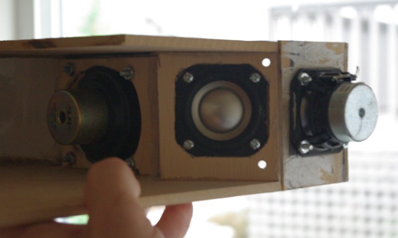
Here is an Akabak model for a tapped horn with three woofers. You can use this model for any tapped horn with three woofers. There are entries for two different woofer types. If I'm not mistaken, no one has published a tapped horn model which allows woofer types that aren't identical.
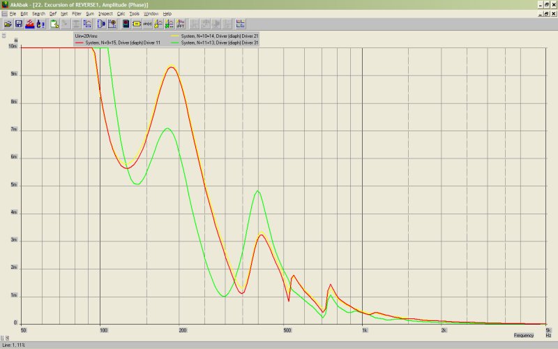
I believe you would get the best results by putting the bigger driver "deeper" in the line, and the smaller driver at the apex. By using two different drivers you spread out the impedance peak, and that improves power handling a bit, and smooths out the response, particularly in the bass.
System 'S1'
|================================================= ================================================== =====
|REQUIRED AKABAK SETTINGS:
|File > Preferences > Physical system constants:
|Sound velocity c = 344m/s
|Medium density rho = 1.205kg/m3
|Sum > Acoustic power:
|Frequency range = 10Hz to 20kHz
|Points = 533
|Input voltage = 31.62V rms
|Integration = 2Pi-sr
|Integration steps = 1 degree ... 1 degree
|Integration method = Cross
|================================================= ================================================== =====
Def_Const |Hornresp Input Parameter Values
{
|Length, area and volume values converted to metres, square metres and cubic metres:
Rg = 0.01e-0; |Amplifier output resistance (ohms)
S1 = 3.23e-4; |Horn segment 1 throat area (sq cm)
S2 = 9.70e-4; |Horn segment 1 mouth area and horn segment 2 throat area (sq cm)
S3 = 19.40e-4; |Horn segment 2 mouth area and horn segment 3 throat area (sq cm)
S4 = 25.02e-4; |Horn segment 3 mouth area and horn segment 4 throat area (sq cm)
S5 = 35.03e-4; |Horn segment 4 mouth area and horn segment 5 throat area (sq cm)
S6 = 45.54e-4; |Horn segment 5 mouth area and horn segment 6 throat area (sq cm)
S7 = 82.23e-4; |Horn segment 5 mouth area and horn segment 6 throat area (sq cm)
S8 = 116.00e-4; |Horn segment 5 mouth area and horn segment 6 throat area (sq cm)
S9 = 116.10e-4; |Horn segment 6 mouth area (sq cm)
L12 = 3.18e-2; |Horn segment 1 axial length (cm)
L23 = 6.36e-2; |Horn segment 2 axial length (cm)
L34 = 6.99e-2; |Horn segment 3 axial length (cm)
L45 = 30.62e-2; |Horn segment 4 axial length (cm)
L56 = 30.62e-2; |Horn segment 5 axial length (cm)
L67 = 6.06e-2; |Horn segment 6 axial length (cm)
L78 = 2.25e-2; |Horn segment 6 axial length (cm)
L89 = 0.63e-2; |Horn segment 6 axial length (cm)
|Parameter Conversions:
Sd = 54.00e-4; |Total diaphragm area for 2 parallel drivers (sq cm)
}
Def_Driver '830970'
Sd=13.00cm2
Bl=2.03Tm
Cms=8.30E-04m/N
Rms=0.27Ns/m
fs=170.0000Hz |Mmd = 73.86g not recognised by AkAbak, fs calculated and used instead
Le=0.01mH
Re=3.10ohm
ExpoLe=1
Def_Driver 'NS3'
Sd=28.00cm2
Bl=2.91Tm
Cms=1.10E-03m/N
Rms=0.20Ns/m
fs=140.0000Hz |Mmd = 73.86g not recognised by AkAbak, fs calculated and used instead
Le=0.30mH
Re=6.30ohm
ExpoLe=1
System 'System'
Resistor 'Amplifier Rg'
Node=1=2
R={Rg}
Driver Def='830970''Driver 11'
Node=2=0=9=15
Driver Def='830970''Driver 21'
Node=2=0=10=14
Driver Def='NS3''Driver 31'
Node=2=0=11=13
Waveguide 'Horn segment 1'
Node=8=9
STh={S1}
SMo={S2}
Len={L12}
Conical
Waveguide 'Horn segment 2'
Node=9=10
STh={S2}
SMo={S3}
Len={L23}
Conical
Waveguide 'Horn segment 3'
Node=10=11
STh={S3}
SMo={S4}
Len={L34}
Conical
Waveguide 'Horn segment 4'
Node=11=12
STh={S4}
SMo={S5}
Len={L45}
Conical
Waveguide 'Horn segment 5'
Node=12=13
STh={S5}
SMo={S6}
Len={L56}
Conical
Waveguide 'Horn segment 6'
Node=13=14
STh={S6}
SMo={S7}
Len={L67}
Conical
Waveguide 'Horn segment 7'
Node=14=15
STh={S7}
SMo={S8}
Len={L78}
Conical
Waveguide 'Horn segment 8'
Node=15=16
STh={S8}
SMo={S9}
Len={L89}
Conical
Radiator 'Horn mouth'
Node=16
SD={S9}
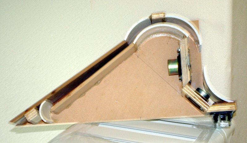
This is a pic of the horn being built. It's going under the dash of my car. The final walls are missing because I needed to figure out which would work the best.
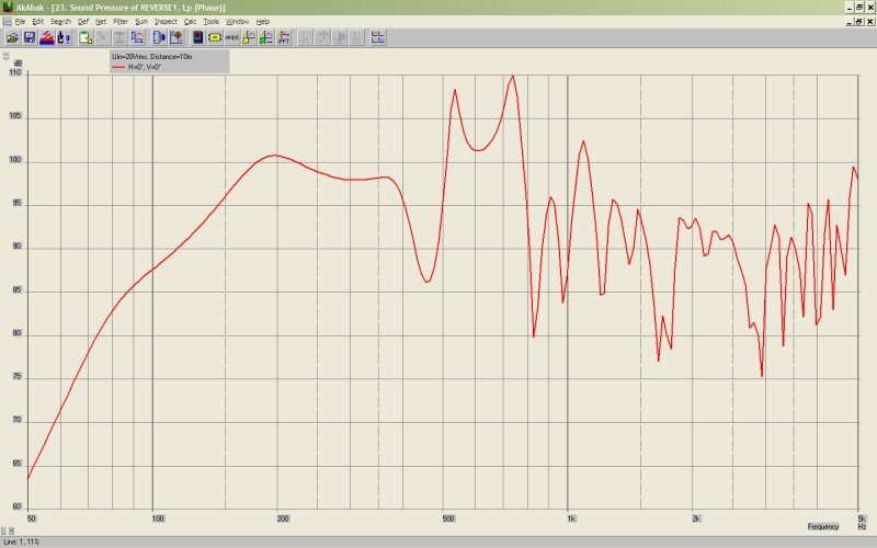
Based on the other tapped horns I've built, I'm expecting that the "real" response above 400hz will not be as peaky as this predicts. Usually it's the midpoint between the peaks. Which means that I should be able to get to 5khz with some response shaping in the crossover.
Or at least that's the goal
- Home
- Loudspeakers
- Subwoofers
- Collaborative Tapped horn project