Greets!
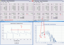
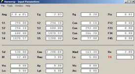
No problem, but I am still not sure which you want since a tapped horn (TH) is an expanding pipe and a tapped pipe (TP) has no expansion (straight pipe) and I am not sure what you mean by 'build' which tells me you are unable to physically make it, though I assume that you mean you are not happy with your HornResp sims, so here is a TH sim and once the initial expansion is properly damped it should have a usable BW out to at least 100+ Hz and maybe as high as its 126 Hz mass corner with an excellent impulse response if the specs are ~accurate and a high order XO slope is used:
GM
Attachments
Involga 10c
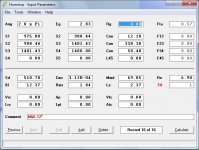
Hi there GM: This enclosure, in post #3402 looks insteresting. Am I interpretating the routine correctly: 14.25-inch square pipe, 62.4 -inches long (48.9+13.5 inches), with the 10-inch driver mounted 13.5 inches from the end, playing into both sides of a central divider wall? The s1 entered as 1, signifies no throat? The mouth S3 is not reduced from the basic tube area (204 cm^2) as is normally done in TH's. Therefore this closed pipe exits down or sideways? CR would be 2:1, acceptable? Would a crossover of 80hz to 100hz be workable? .... regards, MichaelGM said:..........and this is a TP, that again, once damped and the appropriate XO point/slope is added should in theory be smooth, though I doubt it will have nearly as good an impulse response as the much larger TH.
GM
Greets!
Well, it would be only ~5.62" if square, but it's a ~10" driver so will need to be a rectangular slot, ergo will have to have a custom bulge around the backside of the driver near the mouth. This is one of those sims where it's obvious I just 'ran the numbers' and moved on without giving any thought to any layout considerations since they typically don't get built, so not willing to invest hardly any time in them.
Yes, it's a tapped straight pipe and with a simple bi-fold the driver would be mounted to the divider board with the area between the center-line of the driver tapered down to a point at the closed end.
HR sims an end loaded mouth, but a side exit only affects its extreme HF response well above the XO point, so not an issue.
WRT a > 1:1 CR in a TP (this one is 330.1/204 = ~1.618:1), I've only done it with high Qts driver TLs to lower its effective Qts via increased acoustic damping, but the B@$3 Wave Cannon uses 2:1, so see no reason why it wouldn't be fine in a TP as long as the driver's specs called for it.
Dunno about the XO point since I've no personal experience with TP/TH, but for a regular TL the XO point is normally put where the huge 3rd harmonic dip is or ~1 WL away from Fp, so the pipe would need to be lengthened as required to place the dip at these points with reduced efficiency as the trade-off.
GM
Thank you for your advice.
But questions are not answered on linearity FR, pulse characteristics.
Currently, the DIN has played in the design ported, 28 Hz at-3db.
And I want to revamp the design of TP in order to improve the quality of bass.
P.S. Sorry for the language I use a translator
But questions are not answered on linearity FR, pulse characteristics.
Currently, the DIN has played in the design ported, 28 Hz at-3db.
And I want to revamp the design of TP in order to improve the quality of bass.
P.S. Sorry for the language I use a translator
Attachments
Jaycar Drivers
A heads up for Australian / NZ members:
Jaycar have added 2 new drivers to their range, CG2381 / CG2383.
They are 10" and 12", nominally intended for pro sound applications, with relatively high fs (59/55 Hz), low Vas (42L), and high sensitivity (92.7/92.4 dB). Some initial playing with Hornresp indicates that they may prove useful.
Servo THs
Do you think there would be any advantage to using the servo controlled driver/amp combo ala Rythmik? Here's a page talking about "Smart Q", but there is plenty more on the technology at their site.
http://www.rythmikaudio.com/smartQ.html
Here are the paramters of the 15" driver, but as the link implies, those parameters can change with the change of amplifier controls.
fs 15.4Hz
BL 15.8
VAS 430L
Qms 3.748
Qts 0.472
Sd 809 cm2
Re 3.00 ohms
Le 2.5 mH
Xmax 15mm
I have several of these to experiment with, so I thought I would start off asking if it would work in a TH in the first place. The Rythmiks are praised for their high quality bass, but do not have huge output. Perhaps a TH can produce the best of both worlds???
Makc said:Thank you for your advice.
But questions are not answered on linearity FR, pulse characteristics.
Currently, the DIN has played in the design ported, 28 Hz at-3db.
And I want to revamp the design of TP in order to improve the quality of bass.
P.S. Sorry for the language I use a translator
Makc said:Under TP, I mean the Tapped horn, the translator changes the TH to TP
You are welcome! Sorry I missed your posts.
'DIN'? Do you mean the Ivolga 10c driver?
You can add some inductance to smooth out the response, but it hurts the impulse response. You can end load it at the throat and/or make it longer and/or use a different flare factor, but what will make the most difference is proper damping, same as a TL or simple pipe horn.
GM
Re: Servo THs
I assume so, especially to dial in the specs to the horn, but unless it can be used to raise Fs considerably, then building a ~881" long path-length to maximize efficiency would be way too much effort for the rewards IMO.
GM
Fatawan said:Do you think there would be any advantage to using the servo controlled driver/amp combo ala Rythmik?
I assume so, especially to dial in the specs to the horn, but unless it can be used to raise Fs considerably, then building a ~881" long path-length to maximize efficiency would be way too much effort for the rewards IMO.
GM
Servo Tapped Horn
Hi Fatawan and GM,
I probably shouldn't expose my ignorance, but I just don't think that a servo controlled tapped horn is a good idea. The servo sub principle seems to apply best to sealed boxes. I have a hard time imagining how you would go about accounting for all the phase shifts in a tapped horn.
On the other hand the Rythmik 12" driver seems to make a fine driver for a home theater (big) tapped horn subwoofer.
Regards,
Attachments
I actually had a good conversation with brian last december over the concept of a servo controlled tapped horn to see if I could flatten the response in servo. Brian wasn't terribly impressed with the phase/impedance curves presented in a typical tapped horn. Here are some clips of that conversation.
quote:
Servo does not change the physical world. Your way the inductance flatten the response curve is to tame down output at 40hz and 100hz is by adding reactance. You can most likely get the same result by adding a resistor. I am not familar with horn designs. But when I see a 3 high peaks in the impedance plot, that means the horn has a big discontinuity in the design, either it is not long enough, or other reason.....Set that aside, if your problem can be resolve by adding a 4mh inductance, servo can add that in virtual world so that it does not impact the actual raw efficiency. But it cannot increase the efficiency at 60hz. To improve that, you need to tune your horn. That is, you can use a physical horn design to get everything as high efficiency as possible in physical parameter. If there is another set of T/S parameters/ voice coil inductance arrangement, we can implement that in servo.
I have 4 M&K 12" woofer from an online surplus store ($60 woofers).
I haven't figured out what I want to do with them but now I would like to know if they would work in a Tapped Horn design?
I have never built one but I have built sealed subs, ported subs and IB subs. Its time to learn and build a TH sub.
Will 4 of these work in one tapped horn box?
I haven't figured out what I want to do with them but now I would like to know if they would work in a Tapped Horn design?
I have never built one but I have built sealed subs, ported subs and IB subs. Its time to learn and build a TH sub.
Will 4 of these work in one tapped horn box?
An externally hosted image should be here but it was not working when we last tested it.
An externally hosted image should be here but it was not working when we last tested it.
Yes, but it looks like ~2k L is what it will take due to the high Qts, though of course you could make isobaric pairs to drop it to 'only' ~1k L. Better IMO to make some T-TQWTs unless sheer SPL is the primary goal.
BTW, for my records, are these measured specs? Also, what is its Pe, Xmax?
GM
BTW, for my records, are these measured specs? Also, what is its Pe, Xmax?
GM
What are your goals with the TH? I assume your looking for 20hz for home theatre - this needs a BIG box for a TH...
I've attached a quick sim for a box with 1 driver - it's already 500L internal. You can go smaller or larger to taste but bigger = more sensitivity. This is with 1 watt / 8 ohm (Eg = 2.83)
Download hornresp and have a go - check the displacement graph for your intended spl - I couldn't see Xmax or Xmech on that spec sheet. Here's a link to some other large TH so you know what to expect. http://www.cowanaudio.com/th.html
Attachments
I see a very large S1 to Sd ratio. Is that due to the Qts being large?fb said:I've attached a quick sim for a box with 1 driver
GM said:Yes, but it looks like ~2k L is what it will take due to the high Qts, though of course you could make isobaric pairs to drop it to 'only' ~1k L. Better IMO to make some T-TQWTs unless sheer SPL is the primary goal.
BTW, for my records, are these measured specs? Also, what is its Pe, Xmax?
GM
The model I believe is the OC12WF-4B
I think the Xmax is 6.7 mm (not much!!)
Pe
Power Max 200W
Power Rated 100W
What are your goals with the TH? I assume your looking for 20hz for home theatre - this needs a BIG box for a TH...
Thanks for the sim, I will download and learn about all this.
My goal isnt lofty..I already own an IB array in one room and my HT room has twin ported subs that do 15Hz already.
I just have 4 of these drivers in my garage and I have always been interested in learning about Tapped Horns.
Even a 30Hz to 100hz solution would be cool if possible. I will make it part of my HT stage.
- Home
- Loudspeakers
- Subwoofers
- Collaborative Tapped horn project