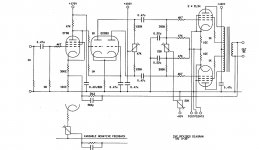
RV32 is the volume control. RV28 is treble and RV 30 bass.
Thanks for the help... Now next step is material arrangement... Searching for baseplate (aluminum or steel?)...
Not just ratings, but also impedance ratio and whether suitable for UL operation. If you have transformers, then find out what they are then find a circuit to suit them. Or start with your chosen circuit then obtain the right transformers. For a beginner trying to mix a random transformer with a random circuit is likely to lead to frustration.
Not just ratings, but also impedance ratio and whether suitable for UL operation. If you have transformers, then find out what they are then find a circuit to suit them. Or start with your chosen circuit then obtain the right transformers. For a beginner trying to mix a random transformer with a random circuit is likely to lead to frustration.
Thanks for suggestion...
Power supply
Hello all,
Is an old post but very interesting still.
One question regarding Power supply : shouldnt EF86 & ECC83 tube heathers elevated?
And for those who already finished that amp : is enough just 220uF in series for first stage filtering?No hum whatsoever?
Regards,
Hello all,
Is an old post but very interesting still.
One question regarding Power supply : shouldnt EF86 & ECC83 tube heathers elevated?
And for those who already finished that amp : is enough just 220uF in series for first stage filtering?No hum whatsoever?
Regards,
Hello all,
Is an old post but very interesting still.
One question regarding Power supply : shouldnt EF86 & ECC83 tube heathers elevated?
And for those who already finished that amp : is enough just 220uF in series for first stage filtering?No hum whatsoever?
Regards,
Could you explain what you mean with the EF86/ECC83 heaters? Do you mean they should have a higher voltage?
Ever since I built the amplifier, there was an issue with a small amount of 100 Hz hum from the power supply. Realizing that I did not double the capacitance in the power supply, as described if it was to be used for a stereo amplifier, I wanted to correct that mistake. With only two 220 uF capacitance on the 450 VDC rail I would see 2,3% ripple. With the recommended four times 220 uF there would be 1,05% ripple. As I had spare 1000 uF capacitors I used those to bring it further down to a mere 0,4% ripple.
While this lowered the voltage ripple by almost 2%, it properly also only reduced the hum by 2%. The major culprit of hum is still ground loops or unshielded parts.
Hello Madskaiser,
I read all what you write , including what are you posted on Youtube !!!!
Great job and good to chime in.
Ok ,I am not an expert , I build 3 tube amps but with 6V6 and a SE 6L6.This amp is the bigger and complex I will build so....I dont know what will be at the end.
So,the schematic point to 220uF in series for first rail of 440V but....for monoblocK!!.I wonder if it is enough.
Regarding the elevated voltage for EF86 & ECC83 you can look after Bruce Power Supply on DIY Audioproject site,you will find many of them.And yes,this mean that the voltage of drivers are at higher potential for about 85V.
If you still have hum with so much capacitance,maybe this is the solution.
Please post a schematic with your Power supply,I do not understand where you put 1000uF...and the Power Trafo is not too hot????
Regards,
Cristi68p,
Concerning the heaters of the EF86 and ECC83: There are two reasons to have this elevated to say +50V:
Firstly the heater-cathode voltage: The cathode of the ECC83 phase splitter is elevated, but the heater-cathode voltage limit for ECC83 is 200V. At a cathode voltage of some +60V for the original, no problem. (I refer to the original, did not go through the whole thread at this time, unsure if some alterations to the original schematic occurred along the way.)
Preventing possible diode conduction between heater-cathode, which will introduce hum in a 'signal-live' cathode: Yes, it is always a good idea to raise heater voltages to some tens of volt d.c. to avoid any heater-cathode leakage by diode effect. This is tube-dependant, but again a simple enough operation to be done as standard. One uses a resistive potential divider from h.t. or another suitable source, with a small bypass capacitor to common, say some 5 - 10µf.
The bypassed cathode potential of a power tube is often used, but for EL84 that is only about +11V - too low to be effective.
P.S: I posted simultaneously with the previous, thus did not read it. My above then some repetition. Sorry!
Last edited:
Hello Johan,
Thanks for your info....I look in the original schematic and I cant see where ECC83 heather is elevated...
There are only 2 x 120 Ohm resistors there, going to the ground , for the heathers.
Maybe I miss something or look to another schematic.
Mine is from Lundahl and is an PDF file with Claus Byrith explanations.
And for clarification,the elevated potential on heathers will avoid the hum problems?
Regards,
Cristi68p,
Perhaps a misunderstanding. I was replying to your post #186, where you asked whether the heaters should not be elevated. I took the question to not refer directly to the original, where as you say the heaters are not elevated. I then implied that where a cathode potential (e.g. in a cathodyne phase splitter) might exceed the maximum relevant spec., heaters needed to be elevated such that the spec was met. (The spec. includes maximum a.c. voltage between heater-cathode where the cathode carries signal, not just the no-signal d.c..)
And no, it will not necessarily solve the hum problem (sorry!), only if said hum is caused by heater-cathode diodic leakage somewhere. A tube tester might show such leakage but not necessarily. But because it is simple, one mostly places heaters at some positive voltage, to obviate possibility of that particular cause of hum.
Thanks Johan for the explanations.....now I understand why need the elevation for some other schematics...") )
)
On the cathode appears an extra voltage from the signal + DC cathode voltage and the specs for heather to cathode voltage is not respected.
In that schematic we have an cathode coupled phase-splitter and signal are taken from the anode.....so no need elevation for the heathers.
Still I wonder if it is enough capacitance (2 x 220uF in series without resistor)for filtering first rail of 440V....the Duncan PSUD shows a little bit more ripple.
I am taking about mono stage.
I want to build this amp with 2 Power supplies , one for each channel , and 2 power rails of 350V from the transformer.......
I dont trust in one common rectifier for 2 channels without a choke in line.
Regards,
)On the cathode appears an extra voltage from the signal + DC cathode voltage and the specs for heather to cathode voltage is not respected.
In that schematic we have an cathode coupled phase-splitter and signal are taken from the anode.....so no need elevation for the heathers.
Still I wonder if it is enough capacitance (2 x 220uF in series without resistor)for filtering first rail of 440V....the Duncan PSUD shows a little bit more ripple.
I am taking about mono stage.
I want to build this amp with 2 Power supplies , one for each channel , and 2 power rails of 350V from the transformer.......
I dont trust in one common rectifier for 2 channels without a choke in line.
Regards,
Regarding the equivalent of 110µF input capacitance in the power supply, only those who have built this can say to what degree hum is audible. Yes, it would be less with more capacitance or a choke or such, but one needs to consider to what degree hum would be audible (as in bothersome) in practice.
Thus two supplies may not offer a practical advantage; again this would depend on the internal impedances of the power transformer. I myself have run two 100W tube amplifiers (8 x 6L6GC) off a single power transformer, rectifier and filter circuit (though including a choke) without audible effects, but the power transformer was in fact a 500VA type, with the rest to suit.
Thus other members need to reply to this.
Johan,you own a monster there !!!
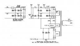
So I attached here the amp & power supply schematic.
Acording Duncan PSUD , with a power transfomer with 370V@250mA (which has a Ri aprox 40-50 Ohm) followed by first cap with 110uF --> 100 Ohm resistor --> second cap 110 Ohm you have first rail of 450V with less,less,less ripple than original schematic.
Even use 50 Ohm resistor , ripple looks damn good.
Now,acc Claus Byrith explanations,he wanted a power supply with minimum impedance and maybe that is why he avoided to use resistor in power supply.
My knoledges are limited to understand if this amp schematic have some drawbacks using a 100 Ohm resistor in power supply.....but being Class A the current should be almost constant , even if fluctuate a little bit with increasing volume , the second cap should be enough as reservoire cap to cover that....
Using more capacitance for first cap to reduce ripple , this means a hotter power transformer and a lot of stress for rectifier diodes.I know that from experience and reading theory.Well,not enough theory to understand all about tube amps.....
I saw all Bruce Heran"s power supplies schematics (from DIY Audio project site),and read all he said about power supply.He designed for first cap max 100uF....like here.But always first cap is followed by a 100 Ohm resistor and than a second 100uF cap for amplifiers with about the same output power.So,why not for this power amp?There are some drawbacks?
Regards,
Attachments
The pre-set pots dissipate <50mW each (Ohm's Law), so 250mW is more than safe. But well-known brands; one does not want the slider contact on the resistance track to shift with time.
(Side note: You mention cut-on-the-shaft as for panel-mounted pots with knobs, or screwdriver adjusted trimpots? Since these will hopefully not need frequent adjustment, any proper quality trim-pot wired in-circuit should be sufficient. Unsure of what you mean.)
(Side note: You mention cut-on-the-shaft as for panel-mounted pots with knobs, or screwdriver adjusted trimpots? Since these will hopefully not need frequent adjustment, any proper quality trim-pot wired in-circuit should be sufficient. Unsure of what you mean.)
I buildt one pair of Byrith's 4-30 monoblocks 9 years ago
I chose the psu version with choke ( lundahl 8H if memory serves)
Quiet enough on my Supravox 215 exc's 95db/1W/1m.
During the building process I got hooked and have buildt several other tube amplifiers.
The last years with DHT's. I listen to these amplifiers now and then.
I did replace the cathode resistor of the ecc83 with a ccs after a while, but the rest of the amplifiers are pr Byrith's schematic
(Side note: You mention cut-on-the-shaft as for panel-mounted pots with knobs, or screwdriver adjusted trimpots? Since these will hopefully not need frequent adjustment, any proper quality trim-pot wired in-circuit should be sufficient. Unsure of what you mean.)[/QUOTE]
Yes,I mean panel-mounted pots with cut-on-the -shaft......the shafts will protude the upper plate of the case.
@Vega65 : what do you mean by quiet enough?Do you mean that some humm is heareble with the ear very close to the speaker (5 cm) ?
Regards aand thanks for info to all...)
Yes,I mean panel-mounted pots with cut-on-the -shaft......the shafts will protude the upper plate of the case.
@Vega65 : what do you mean by quiet enough?Do you mean that some humm is heareble with the ear very close to the speaker (5 cm) ?
Regards aand thanks for info to all...
)
Last edited:
Hello all,
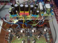
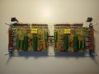
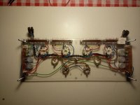
Finally the amp is finished (breadboard variant).I used a double power supply,one for each channel.In addition I build an inrush current limiter that acts only for heaters and a HT delay circuit using an NC555 IC that will conect the anode voltage after 40 sec.
PT specs are :2 x 350V@250mA , 2 x 130V@50mA , 6,3V@7A(with CT) , 6,3V@2A(with CT) , 12V@300mA (for HT delay circuit).
First capacitor in PS is 160uF (means 2 x 330uF in series with 2 x 220K resistors for equalisation --> after first power on I realised is not enough , I had audible hum noise.
Build another stage of filtering with 100R resistor followed by another block of 330uF capacitors --> still not enough filtering , audible hum noise.
In that moment I realised that the humming noise is coming from somewhere else....ground loops or the long wires or even the EF86 tube.
And after 2 weeks of documentation and experimentations I find out what was the problem with that humming noise.
This amp needs a very carefull grounding wiring.You have to follow Claus Byrith layout indications and separate completely the signal ground bus from the power supply ground bus.
The chassis point conection is the input ground--> any other point will induce hum.
The connecting point of power supply ground bus to the signal ground bus is the last 220uF capacitor from negative Vg rail --> any other point will induce hum !!
Believe me,I experimented all variants during last 2 weeks.
And yesterday afternoon after power on.......no hum whatsoever.
I mean no hum with the ear at 2 cm from the speaker.....0 hum.
I dont think that only 220uF for B+ is enough.Maybe you will not hear hum from listening position,but with the ear close to the speaker the hum is heareble.I dont like this,I want 0 hum.
My modular construction helps me a lot doing all these experiments,so be very carefull when building and pay a lot of atention for grounding wiring.
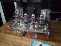
I put some pictures of my build (breadboard) and I will upload when the metal case will be ready....maybe after 2 monts....)
Finally the amp is finished (breadboard variant).I used a double power supply,one for each channel.In addition I build an inrush current limiter that acts only for heaters and a HT delay circuit using an NC555 IC that will conect the anode voltage after 40 sec.
PT specs are :2 x 350V@250mA , 2 x 130V@50mA , 6,3V@7A(with CT) , 6,3V@2A(with CT) , 12V@300mA (for HT delay circuit).
First capacitor in PS is 160uF (means 2 x 330uF in series with 2 x 220K resistors for equalisation --> after first power on I realised is not enough , I had audible hum noise.
Build another stage of filtering with 100R resistor followed by another block of 330uF capacitors --> still not enough filtering , audible hum noise.
In that moment I realised that the humming noise is coming from somewhere else....ground loops or the long wires or even the EF86 tube.
And after 2 weeks of documentation and experimentations I find out what was the problem with that humming noise.
This amp needs a very carefull grounding wiring.You have to follow Claus Byrith layout indications and separate completely the signal ground bus from the power supply ground bus.
The chassis point conection is the input ground--> any other point will induce hum.
The connecting point of power supply ground bus to the signal ground bus is the last 220uF capacitor from negative Vg rail --> any other point will induce hum !!
Believe me,I experimented all variants during last 2 weeks.
And yesterday afternoon after power on.......no hum whatsoever.
I mean no hum with the ear at 2 cm from the speaker.....0 hum.
I dont think that only 220uF for B+ is enough.Maybe you will not hear hum from listening position,but with the ear close to the speaker the hum is heareble.I dont like this,I want 0 hum.
My modular construction helps me a lot doing all these experiments,so be very carefull when building and pay a lot of atention for grounding wiring.
I put some pictures of my build (breadboard) and I will upload when the metal case will be ready....maybe after 2 monts....
)Attachments
Cristi68p,
Somewhat OT - but yah! Hum!!
One sometimes even needs to determine the phase with respect to the main supply (induced hum etc.) I once went round with an earth wire touching a great many places on the chassis until I finally found one spot where all hum was eliminated. Poor layout to begin with, poor placing of components? I couldn't care - went and screwed down that blooming earth wire right at the (sweet) spot and heaved a mighty sigh of relief.
Glad you are coming right!
- Status
- This old topic is closed. If you want to reopen this topic, contact a moderator using the "Report Post" button.
- Home
- Amplifiers
- Tubes / Valves
- Claus Byrith 30W PP