i think that the ic might be damged.
i've been searching when you purchased the TA2022 amplifier board, to see from which version belongs and if i have any particular comments regarding that version. i haven't found your order... then i searched again, and i saw that you bought this board without ic, and u used the ic form the first board which you haven't used anymore, due to similar noise issues. contact me by mail, i can send you replacement if you can't make-it work.
i've been searching when you purchased the TA2022 amplifier board, to see from which version belongs and if i have any particular comments regarding that version. i haven't found your order... then i searched again, and i saw that you bought this board without ic, and u used the ic form the first board which you haven't used anymore, due to similar noise issues. contact me by mail, i can send you replacement if you can't make-it work.
I have a few questions about TA3020V3B.
1, What is the max output power in BTL with the IRFP4228 output FETs? The documentation says 540 W in 8 ohm/960 W 4 ohm. But when you look at the documentation for the TA3020V3C it says 780W 8 ohm/1160 W 4 Ohm if using the IRFP4228 FETs. I gues the documentation for V3B just havent been updated with the output numbers for the IRFP4228 FET option?
2, For BTL mode with the TA3020V3B and output of 540 W in 8 ohm/960 w 4 ohm, what should the secondaries of the transformer be? I guess 2 x 42 VAC is the correct voltage?
3, The BIPS is good for driving 2 TA3020V3B boards in BTL mode?
Thanks.
Last edited:
3, The BIPS is good for driving 2 x TA3020V3B boards in BTL mode?
Thanks.
Another question.
Since the TA3020V3C has already been made ready to work in BTL mode just by a single resistor that makes one channel work out of phase with the other, doesnt that remove the buspumping issue and thereby making it possible to use V3C in BTL without that issue. Would save people from buying a BIPS.
The caps on V3C, how big are they diameter wise, 35 mm? If one were to change them to some higher value caps.
Yes, on the TA3020v3c there is a small solder bridge on the bottom layer of the pcb which allow easier connection for BTL mode. in this way the amplifier can be used without the BIPS. the role of the BIPS is not only to allow easier BTL connection, but also to be used as input interface, the XLR balanced input can be used or Cinch connectors for unbalanced. also there are 2 switches from which can select the mode, Stereo or BTL and balanced/unbalanced. this functions cannot be replicated by the solder bridge on the bottom of the amplifier pcb only.
the capacitors are standard 35mm diameter, and can choose their value from 10mF to 18mF each. other capacitors can be used as well, which have minimum working voltage of 63V and same footprint.
the capacitors are standard 35mm diameter, and can choose their value from 10mF to 18mF each. other capacitors can be used as well, which have minimum working voltage of 63V and same footprint.
On the first and second batch of the TA3020v3c pcb's there need to solder one resistor, same value as the one between pins 22 & 23 or 25 & 26. on the last versions, the resistor is already there and i small solder bridge must be connected which is in series with this resistor. I remember that your boards are from the first batches, and the resistor must be added. please to this careful, to not damage the pads or the pcb.
Thankyou cristi.
Can you confirm all changes needed from running in stereo to BTL using bips?
1) add resistor at r74
2)take speaker output from outR and outL (pin 1 and 7 on output side)
3)amplifier signal imput will be on the R side.
Is this correct?
Are any changes needed to the amp imput wiring from the bips unit?
Thanks.
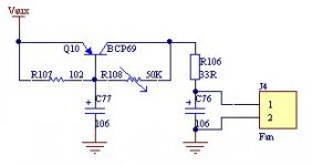
Do you have a schematic for the Fan controller implemented in TA3020V4?
Im probably going to buy a single TA3020V3C sometime in the future.
Doing softstart and input phase shifter myself, however I havent really found a simple diy fan control so having a schematic would be nice.
Im probably going to buy a single TA3020V3C sometime in the future.
Doing softstart and input phase shifter myself, however I havent really found a simple diy fan control so having a schematic would be nice.
The fan controller implemented on TA3020v4 is very simple. has one PNP transistor biased by a small NTC, 50K at 25*C and 2.7K at 100*C. the supply voltage is within 12-14V range, fan 12V DC at 60-120mA. the fan start to spin when the voltage across its terminals is about 4-6V depending on the model. the temperature when starts to spin is about 48-55*C. as the temperature increase, the speed of the fan also increase, providing more airflow. the noise generated is very low due to the low speed. the thermistor must be as close as possible to the output transistors and not to close to the controller transistor to avoid mutual heating and autoderating.
Attachments
R74 must have same value as R20 and R24, the input signal will be applied at pin4, Left In, and pin 6, Right In will not be connected. Output will be taken from pins 1 and 7, without connecting to GND.
if you are using this configuration, no need to bridge the amp using BIPS module. if you want to use-it just to have balanced input, just connect it simply output of BIPS to the input of the amp.
if you are using this configuration, no need to bridge the amp using BIPS module. if you want to use-it just to have balanced input, just connect it simply output of BIPS to the input of the amp.
The TA3020v3c has few options regarding the capacitors choice. if none of them is suitable for your needs, then yes, i can deliver the board without the caps, at a lower price. the installation of the new caps will be made on the user's responsibility very careful at the polarity. there are polarity markings on the pcb and caps, so this should not be a problem for anyone.
Volume control ?
Looking at the new TA3020 with integrated BIPS: do I understand correctly that there is volume control associated with BIPS?
Is this feature available with standalone BIPS too ?
Well, you're not so far from the "all in one" module made of BIPS + TA3020 + SMPS")
Looking at the new TA3020 with integrated BIPS: do I understand correctly that there is volume control associated with BIPS?
Is this feature available with standalone BIPS too ?
Well, you're not so far from the "all in one" module made of BIPS + TA3020 + SMPS
- Status
- This old topic is closed. If you want to reopen this topic, contact a moderator using the "Report Post" button.
- Home
- More Vendors...
- Connexelectronic
- Class T Audio Amplifiers