...should be much better..., or not really ?
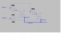
During high di/dt an inductive voltage drop across the source leg of the MosFet will happen. This drop is typically in the range of multiple volts.
Real life layout will have similar or worse inductance on the track, which you called power path. Means we will have a similar drop there.
The two separation resistors will define the reference for the gate driver more or less in the middle between the both potentials of the source pads.
This is resulting in different gate drive levels (gate pad vs. source pad).
The left MosFet will see less gate drive compared to the right side.
...not confident anymore that this configuration will solve the di/dt sharing...
Is that OK?
So this is you mean with difficulty with switching high current fast?
If your drivers has common ground and between 2 mosfet driven sources differ to 10V, yo need to separate the drivers. Driver rev(gnd) should be taken from sorce pin, not from place that may reach d10V from souce pin.
So this is you mean with difficulty with switching high current fast?
If your drivers has common ground and between 2 mosfet driven sources differ to 10V, yo need to separate the drivers. Driver rev(gnd) should be taken from sorce pin, not from place that may reach d10V from souce pin.
Oh?, may be they also using tracking rail, if 1bjt could deliver 10A peak, 10pair will be 100A. Dunno better ask them for that spec. My 200W into 4ohm amp only 14A maximum, current is limited.(and the manufacturer that says 80A or 120A for a few bipolars has become a joke over time). In the beginning, I got into amplifiers mostly by repairing class AB, I still fix one from time to time.
Markus,
The drive current while charging Cgs brings additional drop on the separation resistor, which helps balancing the Vgs's.
Probably the exists some optimum value of this resistor here.
Of course this is not a cure-all scheme, works in conjuction with normal layout precaucions and common sense.
The drive current while charging Cgs brings additional drop on the separation resistor, which helps balancing the Vgs's.
Probably the exists some optimum value of this resistor here.
Of course this is not a cure-all scheme, works in conjuction with normal layout precaucions and common sense.
Is that OK?
So this is you mean with difficulty with switching high current fast?
If your drivers has common ground and between 2 mosfet driven sources differ to 10V, yo need to separate the drivers. Driver rev(gnd) should be taken from sorce pin, not from place that may reach d10V from souce pin.
...your proposal demands to have two floating drivers, means two level shifter + drivers. Both sequences must have matched propagation delays, better than 10ns, preferably below 5ns.
Well, if you start to spend that amount of material, you are already close to a multiphase power stage, which does not need matching of propagation delays, but must have perfect DC balance for both tails...
Furtheron a multiphase system has switching residuals in the feedback of double modulator frequency - depending on the used technique to overcome feedback induced modulation distortion a multiphase system might have higher distortion or might need a specialized solution to overcome feedback induced modulation distortion. (Fortunately these distortion issues are relevant if you target THD around -80db at output levels > 30% max power, but not if you can live with -50db.)
...there are no limits to boost system complexity.
Finally it will always be a trade off between requirements, complexity, costs and as darkfenriz says common sense.
(The funny thing with common sense is that the number of conclusions equals the number of involved people. Commonly. Sometimes even exceeds...)

Back to topic...
From technical view classD and classAB both offer the possibility to design for high currents. Also in both techniques you do not get it for free, but have to spend efforts and accept related compromises.
The design decision between a peak current capability of 200A or just 10A (or something inbetween? ) for an amp rated 100W into 8 Ohms is just a matter of common sense (in accordance to my comment on common sense in my last posting ).
...here my portion of our common sense:
My horse sense tells me that allowing at any phase angle two times of the value that a perfect constant and ohmic load would need is sufficient to handle most speakers even with slightly sick crossovers.
Of course there is always a possibility to design a cross over even more sick...
A linear amplifier is formed during MOSFET turn-on and sometimes at turn off to. Shared souce lead (and layout) inductance and resistance (common to gate and output current) is in the feedback loop. It may even be instable in some designs, resulting in amplified ringing and plenty of EMI
There are two RF linear amplifiers inside every class D output stage.
There are two RF linear amplifiers inside every class D output stage.
Ai Se Eu Te Pego
I am not Michel Telo, obviously I am talking about the said RF amplifier.
Learned to tame all my RF amplifiers after some fundamental hints from Spain.
(Always following the forum rules ==>English: 'Ah, when I get my hands on you.'
It's a popular song in the european charts.)
I am not Michel Telo, obviously I am talking about the said RF amplifier.
Learned to tame all my RF amplifiers after some fundamental hints from Spain.
(Always following the forum rules ==>English: 'Ah, when I get my hands on you.'
It's a popular song in the european charts.)
I don't know what is darkfenriz problem, class D isn't my world so I don't know that there was so many problem with RF treasure. In linear amplifier, RF should not disturb VAS. 4 floating drivers just less complex when in modules.
RF amplifier, heh? you better go catch and tame thaht.
http://dc424.4shared.com/img/109072...3Ftsid_3D20120121-104557-95ec6f60/preview.mp3
Looks like Telo's voice is distorted, not a good with recording.
RF amplifier, heh? you better go catch and tame thaht.
http://dc424.4shared.com/img/109072...3Ftsid_3D20120121-104557-95ec6f60/preview.mp3
Looks like Telo's voice is distorted, not a good with recording.
...Europe is beeing flooded with this version
Michel Teló - Ai Se Eu Te Pego - Oficial (Assim você me mata) - YouTube
The German translation is linking better to undesired and/or invisibile oscillations of RF-amps that are formed as side effect of our half bridges.
...translating the German translation to English: 'When I get you'
This can be difficult. First seeing them at all, second taming them.

darkfenriz, Eva and Choco are just some hypochondric nerds. Always pointing to parasitic inductances, capacitances, parasitic RF amps, resonances, hard switching, Qrr or even to basic physics. To blind to see how simple life can be.
The most simple and not uncommon method to cure undesired RF issues is to use a slow scope.
By this you can even put a great documentation that satisfies ISO9001 and
proove that you ensure top design quality by a proper procedure.
If nobody forces you to fulfill ISO9001 it is even better not to measure at all.
I think this method should also be applicable in linear tube amps with
fast designs that use triodes like the ECC82 without gate stoppers, but huge wiring loops.
In linear transistor amps it might be fortunate to use a scope with a bandwidth well below 1MHz. Also do not investigate into depth about the strange biasing behavior of the VAS and/or output stage...
The only few things a true high end engineer really should care about is to use the right high end signal capacitors and decent supply caps sized 10 ft³/W (of course additionally bypassed right at the screwing terminals of the monstercaps), omit overcurrent protections and state that the design is fast
and can deliver 200A within micro seconds. Sound will immediately step to unmatched levels.
Michel Teló - Ai Se Eu Te Pego - Oficial (Assim você me mata) - YouTube
The German translation is linking better to undesired and/or invisibile oscillations of RF-amps that are formed as side effect of our half bridges.
...translating the German translation to English: 'When I get you'
This can be difficult. First seeing them at all, second taming them.
darkfenriz, Eva and Choco are just some hypochondric nerds. Always pointing to parasitic inductances, capacitances, parasitic RF amps, resonances, hard switching, Qrr or even to basic physics. To blind to see how simple life can be.
The most simple and not uncommon method to cure undesired RF issues is to use a slow scope.
By this you can even put a great documentation that satisfies ISO9001 and
proove that you ensure top design quality by a proper procedure.
If nobody forces you to fulfill ISO9001 it is even better not to measure at all.
I think this method should also be applicable in linear tube amps with
fast designs that use triodes like the ECC82 without gate stoppers, but huge wiring loops.
In linear transistor amps it might be fortunate to use a scope with a bandwidth well below 1MHz. Also do not investigate into depth about the strange biasing behavior of the VAS and/or output stage...
The only few things a true high end engineer really should care about is to use the right high end signal capacitors and decent supply caps sized 10 ft³/W (of course additionally bypassed right at the screwing terminals of the monstercaps), omit overcurrent protections and state that the design is fast
and can deliver 200A within micro seconds. Sound will immediately step to unmatched levels.
Errr, I got it says "when I catch you". Telo said oscillation?
Ahh yes... Life is simple and easy. Just find the right path and follow. But sometimes people just too ambitious and forgot that he already has more than what he need.
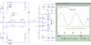
Reaching high quality amps are also easy. Not as difficult as to tame any RF in RF amplifier.. Just make series connection of high efficiency amplifier with classAB that supplied with +-5V.
Picture of simplest (linear ClassG), Also work with digital tracking rails, but may be another time for classD, its output filter is still a big lagging devices.
Ahh yes... Life is simple and easy. Just find the right path and follow. But sometimes people just too ambitious and forgot that he already has more than what he need.
Reaching high quality amps are also easy. Not as difficult as to tame any RF in RF amplifier.. Just make series connection of high efficiency amplifier with classAB that supplied with +-5V.
Picture of simplest (linear ClassG), Also work with digital tracking rails, but may be another time for classD, its output filter is still a big lagging devices.
Attachments
Nice interpretation Choco
This happens when someone's self stem is based in an old, inherited & dysfunctional perception of reality (that fakes results when he doesn't get any, to avoid "wasting" time finding the right method or being perceived as less "macho" for not knowing the right answer). And they are too lazy and coward to de-construct their egos and construct them back on a more accurate knowledge system.
We have a world crisis going on because there are too many brains like that (their "bootloaders" date from 1960s babyboom) which are not year 2000 compliant and refuse reprogramming
Sometimes situation demanding special requirements, that need this and that. Then we have too choose to be qualified or to leave.
Nowadays western measuring system of audio amplifier are distortions, very bad that they including, RF/ EMI and things similar with that.
That western isn't my goal, I only need amplifier that not fatigued audience ears, for 2-3hour listening, 3-5 times a day, almost everyday. Some audience just have not in good mood to listen if their ears fatigued.
About accurate knowledge, I agree it really important to choose the right path and not went astray. Not only amplifier, but whole of life.
We are in agreement hereNot only amplifier, but whole of life.

Telo said oscillation?
...I have no idea what Telo is talking about..
Ahm, Ok Ok.
I love to use phrases different from the original meaning.
Playing with words, theoretically allowing multiple interpretations.
Why do I suddenly feel like looking into a mirror?!But sometimes people just too ambitious and forgot that he already has more than what he need.

But it's a nice face *alwaysproudonmyown*
@Eva:
I have to highlight that I wrote #73 without any
... angry about the human factor on this planet?
I cannot compete on your passion in this regard, but I failed finding valid points to debate on your view.
P.S.
Who is completely free of the patterns you described?
I am not. Especially in the last discipline I am gaining experience.
@ Topic
I have to apologize, we lost you again.
- Status
- This old topic is closed. If you want to reopen this topic, contact a moderator using the "Report Post" button.
- Home
- Amplifiers
- Class D
- class D vs class AB current capability.