
skaara said:I dont know why some people make fun of attempting high power low frequency class d.. I built quite a few smps but never built class d for real use and now i`d try it because it works on same principle. If i understand that properly it wouldnt need that high switching frequency for amplifying signals up to 500hz (or 1 khz)..
Would 10khz switching frequency be enough?
And is negative feedback necessary?
I tried once building class d with sg2524 for fun, it was very simple and it worked but i wonder if this would work for that power too?
10khz switching frequency is impractical. Size of output filter components become huge.
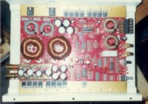
I have done full-bridge with 300v rail witch is good for about 6kW to 8ohms. (have measured 4.5kW to 4.5ohms) If you decide to desing it for 16ohms load things get easier and 300v rail with full-bridge still gives you almost 3kW.
4pcs of STW45NM50FD in full-bridge should be capable of that power if you drive them properly at enough low frequency. Infineon has some even better candidates, but usually with slow body-diode.
mzzj said:
10khz switching frequency is impractical. Size of output filter components become huge.
I have done full-bridge with 300v rail witch is good for about 6kW to 8ohms. (have measured 4.5kW to 4.5ohms) If you decide to desing it for 16ohms load things get easier and 300v rail with full-bridge still gives you almost 3kW.
4pcs of STW45NM50FD in full-bridge should be capable of that power if you drive them properly at enough low frequency. Infineon has some even better candidates, but usually with slow body-diode.
What chipset did you use for the PWM? You wouldn't happen to still have an (eagle) schematic of this beast would you?
")
Sam.
"Chipset"samborambo said:
What chipset did you use for the PWM? You wouldn't happen to still have an (eagle) schematic of this beast would you?
Sam.
http://www.ee.oulu.fi/~masaj/class-d/P1040036.jpg
Some schematics here: http://www.diyaudio.com/forums/showthread.php?s=&threadid=69429&highlight=
I am currently doing layout for SMD PWM-stage board and opto/mag-couplers for drive signals. Plus tiny powersupply with 4x floating 15v outputs for gate drivers.
Anyone intrested in lower-power(100w-1kW) project based on Crown-BCA topology?
mzzj said:
Anyone intrested in lower-power(100w-1kW) project based on Crown-BCA topology?
offcource i would! seems i'm alone though..
Re: Class T Option
Hi, will you please email the Elektor articles to me?
Anzgar
Antz said:You may consider building a Class T amplifier. It also has a switching output topology but the creation of the switching signal follows a digital route. Tripath, www.tripath.com, make the necessary processing chips all you have to do is add the output FETs. Again it is a very power efficient design which results in low weight but high power. There was a 300W per channel, bridge-able to 600W, described in Elektor Magazine starting June 2004 based on Tripath's TA3020. If you would like the articles I have them in soft format, I can email them to you.
Hi, will you please email the Elektor articles to me?
Anzgar
I've looked at Crown BCA power amp (K1-K2), and their output filter is quite complicated. Before the main amp, the signal is passing through "7th order gaussian low pass" and the output node is going through 7th order filter (L-C is 2nd order).
Is that properly designed classD should look this complex?
Is that properly designed classD should look this complex?
lenz said:Hi Anzgar
I`m not "Antz", but I can send you this article in german,french.dutch or english . Your choice.
But I need an adress.
That's nice of you,thanks!
anzgar@gmail.com
Anzgar said:
Lenz,
Since you're offering I'll take the Dutch copy off your hands, you can fire it off to ssassen(at)hardwareanalysis(dot)com.
Thanks!
Sander Sassen
http://www.hardwareanalysis.com
Since you're offering I'll take the Dutch copy off your hands, you can fire it off to ssassen(at)hardwareanalysis(dot)com.
Thanks!
Sander Sassen
http://www.hardwareanalysis.com
"Chipset"
http://www.ee.oulu.fi/~masaj/class-d/P1040036.jpg
Some schematics here: my new 4.5kW class-d amp (crown BCA topology) - diyAudio
I am currently doing layout for SMD PWM-stage board and opto/mag-couplers for drive signals. Plus tiny powersupply with 4x floating 15v outputs for gate drivers.
Anyone intrested in lower-power(100w-1kW) project based on Crown-BCA topology?
hi mzzj,
care to share the project with us since the links you provided are dead.
i am working on something simmilar and i am curious how you have done the power stage and also the feedback loops.
mine (a simulation for the moment) goes up 6.8kw @ 2 R with 180Vdc single supply using fullbridge configuration.
regards,
savu
Last edited:
- Status
- This old topic is closed. If you want to reopen this topic, contact a moderator using the "Report Post" button.
- Home
- Amplifiers
- Class D
- Class D amplifier 1 KW RMS