Sorry to say that this pcb design is dangerous. Primary and secondary circuits are mingled on the board, basic insulation requirements are ignored. Better you never connect this with the mains.
Thank sir for recommend and caution. this pcb Size is determined 180*80 mm and Single Heatsink it non Isolation of 3 section. I wanted your PCB Design for I'm
improvement.
please post a link of your build loeitech
I don't have Website or Link Because I think it bobby. But i can Show the Picture for all people of DIY Audio
PCB... 2 Layer PTH Copper 2 Oz
An externally hosted image should be here but it was not working when we last tested it.
Part Assembly
An externally hosted image should be here but it was not working when we last tested it.
PowerOutput Signal 20 KHz
An externally hosted image should be here but it was not working when we last tested it.
PowerOutput Signal 1 KHz
An externally hosted image should be here but it was not working when we last tested it.
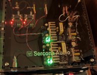
Operation Tested
An externally hosted image should be here but it was not working when we last tested it.
Using In Contdown 2016 In Thailand...about..10 Hour Mid-Hight Driven..
An externally hosted image should be here but it was not working when we last tested it.
Green Nature
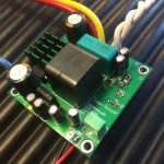
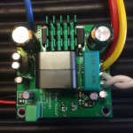
My new Class-D, based on OP-275, MAX913, LM5401 and IRFS5615.
I call it Green Nature
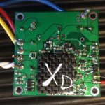
Own modulator; mixed pre- and post-filter, XD refering to X times/multiply/gain and D for class-d.
Small cover plate in carbon ... just for the fun of it
Should be good for 100 W @ 8 ohm and double in 4 ohm .... will have to test of course. Takes up to +-50VDC for PSU, but think I'll keep it at 40 - 45V (limited by capacitors).
Size 5 cm x 5 cm x 2.1 cm
Runs around 300 kHz.
Only a little heat from the gate PSU transistor (BD139).
My new Class-D, based on OP-275, MAX913, LM5401 and IRFS5615.
I call it Green Nature
Own modulator; mixed pre- and post-filter, XD refering to X times/multiply/gain and D for class-d.
Small cover plate in carbon ... just for the fun of it
Should be good for 100 W @ 8 ohm and double in 4 ohm .... will have to test of course. Takes up to +-50VDC for PSU, but think I'll keep it at 40 - 45V (limited by capacitors).
Size 5 cm x 5 cm x 2.1 cm
Runs around 300 kHz.
Only a little heat from the gate PSU transistor (BD139).
Attachments
I heard so much good of those tiny no name class d amps from Alibaba Express, so I decided to give them a try.
I'm totally blown away with the excellent sound produced by this 16 dollar gadget!
There's a clean attack in the low registers, a very smooth treble and the midrange is very detailed and pleasing to the ear.
I know that amps can be very hard to distinguish from each other, but, to my ears anyway, this one certainly sticks it's nose out.
Which PCB's did you use? I like your arrangement.
looks great, every version gets better!My new Class-D, based on OP-275, MAX913, LM5401 and IRFS5615.
I call it Green Nature
Own modulator; mixed pre- and post-filter, XD refering to X times/multiply/gain and D for class-d.
Small cover plate in carbon ... just for the fun of it
Should be good for 100 W @ 8 ohm and double in 4 ohm .... will have to test of course. Takes up to +-50VDC for PSU, but think I'll keep it at 40 - 45V (limited by capacitors).
Size 5 cm x 5 cm x 2.1 cm
Runs around 300 kHz.
Only a little heat from the gate PSU transistor (BD139).
Too bad I can't read from your site, like you have for older versions, I love that (what components you used and why)
New Design ClassD Amp + DSP for Powered Speaker , LineArrey HomeAudio etc.
An externally hosted image should be here but it was not working when we last tested it.
![IMG_2627[1].jpg](/community/data/attachments/508/508002-6b7446cbda7204300bdb21b08ae46a29.jpg)
I've tried LED light strip psu's and even those are fine.
anything is fine. I see no reason to feel clean dc from linear into a switcher amp. seems like any 'purity' is ruined by the class-d, so why go nuts on anything other than stable voltage and sufficient current?
I do insist that the psu not sing, physically. these dont, thankfully.
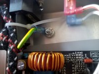
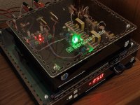
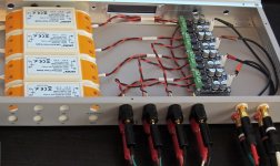
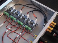
here's another build with those same amp modules but with 4 of them and 4 12v led light strip psu modules. using a repurposed 1u rackmount. this is an ugly-outside, good-inside (lol) build. its for my active XO biamp system.
anything is fine. I see no reason to feel clean dc from linear into a switcher amp. seems like any 'purity' is ruined by the class-d, so why go nuts on anything other than stable voltage and sufficient current?
I do insist that the psu not sing, physically. these dont, thankfully.
here's another build with those same amp modules but with 4 of them and 4 12v led light strip psu modules. using a repurposed 1u rackmount. this is an ugly-outside, good-inside (lol) build. its for my active XO biamp system.
Attachments
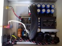
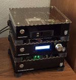
Another small kit...
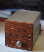
He're my latest "basic kit": Raspberry Pi audio server/streamer with 24/192 DAC (top) and another TPA3116D2-based amp (bottom).
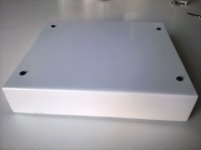
This is planned as an "economy" model compared to my usual round enclosures, which are rather expensive to make. These are easier (and cheaper) to make, but they still require a lot of work by hand....
Size (both boxes stacked on top of each other, LxWxH): 13x10x10 cm!
The kit sounds great
He're my latest "basic kit": Raspberry Pi audio server/streamer with 24/192 DAC (top) and another TPA3116D2-based amp (bottom).
This is planned as an "economy" model compared to my usual round enclosures, which are rather expensive to make. These are easier (and cheaper) to make, but they still require a lot of work by hand....
Size (both boxes stacked on top of each other, LxWxH): 13x10x10 cm!
The kit sounds great
Attachments
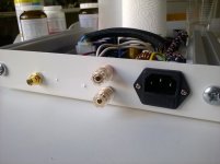
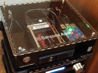
funny you mention rpi and 24/192, here's my stack, just done today.
the photo does not show the PGA preamp display well, and it does not really matter since its going to be replaced by an LED 4digit big bright display. for now, I'm using the stock firmware on the pga (ebay) build but will replace it with my own arduino stuff soon.
what's new is the top media player with a 2 bay notebook drive frame. it was quite a challenge to get the pi, its audio board and the disk frame in a box and have it 'make sense'. I needed to have hdmi accessible (for debug) so that meant the board had to be to the right and right up against the chassis wall (there is a cutout on the right side for hdmi). I decided not to expose the onboard ports from the pi directly and instead used some usb extensions that are panel-mount (not easy to find) and have those extend the usb to the rear. 2 more ports are connected to usb/sata adapters that plug into the sata drive frame. there's 2 spare usb ports on the back (via the extension) and one is used for a wifi dongle, for playing music on my NAS across my home wifi network. you can plug a flash drive or keyboard into the extra usb port.
the internal cabling isn't super pretty, but its acceptable and I found some short 6" usb/usb cables I used for jumping from the drive to the pi.
its a hack, but its a useful hack and I like how I don't have to waste horizontal space on my desk for this setup.
Attachments
Last edited:
- Home
- Amplifiers
- Class D
- Class D Amp Photo Gallery