nuvistor said:I wonder, what is the purpose of the 47p capacitors? the time constant with the 150R is 7ns.
Improve minor-loop stability margins...
darkfenriz said:Mike
Is this a machanism of introducing a zero for 'miller-type' pole?
No...Miller compensation rolls off foward path gain by increasing minor-loop transmission about the second stage....This is denoted by a pole in the foward path gain-frequency response..
It follows that the reduction in foward path gain must simultaneously be accompanied by an increase in minor loop transmission about the second stage...denoted by a zero....
Bypassing the second stage's emitter resistor merely increases minor loop transmission at ultrasonic frequencies...near the local loop's unity gain frequency....ergo...introduces yet another arbitrary zero....which enhances stability in the local loop.....
darkfenriz said:Do you mean local miller integrator might need a zero for better stability?
Yes...and No...you do not have to be 'extremely talented' to make the second stage of an op amp. unstable...Just enclose three or more transistor stages within the loop...
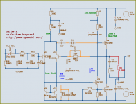
Graham Maynard 25 Watt Class-A JLH based amplifier
Hi, Greg Guru.
I am still not convinced enough to begin to replace
my Class-A discrete pre amplifiers and power amplifiers.
And if I will build myself a new pre/power amp ( in case I have ANY USE for another amp )
I certainly will go 100% Class-A, push-pull complementary or quasi-complementary.
Like for example Graham Maynard Class-A (based on work of JLH, John L. Hood ).
See my ATTACHED SCHEMATIC
This is in my Lineup Audio book,
how a good Audio Amplifier should be!
Audio Regards to Australia, all kangaroos and amplifierguru
lineup
-------------------------------
More info, background and description at Graham Maynard
website
http://www.gmweb2.net/
Latest published version of GM25W Class-A is 2007-01-26
Cheers & have some bears. Russian Bear is great & big!
lineup said:Generally, why is almost no Chip OP-amplifier in Class A
I think is
when you go for an IC ( and not discrete ) Operational amplifier
- you want it simple
- you want it as low power supply as possible
- you might want to build a great number of identical devices
If you want to find TRUE Class A OP-amps, you have to go for discrete.
Like this one by Graham Maynard:
http://www.mitedu.freeserve.co.uk/Circuits/Audio/preamp.gif
Hi-Fi Preamplifier by Graham Maynard
.
amplifierguru said:Hi lineup,
There are many modern op amps
that operate enough standing output stage current
that they will operate Class A into av high Z load
- so they can be lightly loaded with a discrete buffer stage.
Class A may be a goal in itself in low power and preamps but in power amps it's generally a wasteful fallback position.
Cheers, Greg
Hi, Greg Guru.
I am still not convinced enough to begin to replace
my Class-A discrete pre amplifiers and power amplifiers.
And if I will build myself a new pre/power amp ( in case I have ANY USE for another amp )
I certainly will go 100% Class-A, push-pull complementary or quasi-complementary.
Like for example Graham Maynard Class-A (based on work of JLH, John L. Hood ).
See my ATTACHED SCHEMATIC
This is in my Lineup Audio book,
how a good Audio Amplifier should be!
Audio Regards to Australia, all kangaroos and amplifierguru
lineup-------------------------------
More info, background and description at Graham Maynard
website
http://www.gmweb2.net/
Latest published version of GM25W Class-A is 2007-01-26
Cheers & have some bears. Russian Bear is great & big!
Attachments
B.VDBOS skectch for biasing monolithic op amps class A wasn't too far off
I've acutally built a monolithic op amp headphone amp that is biased Class A for up to 400+ mA ~ 5W into 60 Ohms
http://www.head-fi.org/forums/showthread.php?p=2276512#post2276512
scroll around that thread for my (jcx) posts showing a rather extreme implementaiton
basic principle:
I've acutally built a monolithic op amp headphone amp that is biased Class A for up to 400+ mA ~ 5W into 60 Ohms
http://www.head-fi.org/forums/showthread.php?p=2276512#post2276512
scroll around that thread for my (jcx) posts showing a rather extreme implementaiton
basic principle:
Class A IC-Chip op-amps do not exist.
At least not manufactured in any quantity and so commonly found for us.
To single end bias the output stage of one Class AB op-amp
will not give you one Class A op-amp.
Because the op-amp was designed & calculated for a specific output stage operation
= Symmetrical Class B / Class AB, in 90% of all known cases.
If you want Class A op-amp, you must go discrete.
There are plenty of discrete transistor operational amplifiers in Class A.
In fact, it is more The Rule than the exception.
all sorts of, JFET or BJT input, complementary or one LTP differential pair inputs.
Because when a good designer is left with the choice,
he will go Class A all the time, if there is no special thing against it.
And most often is not. Except for Power Op-Amps applications.
Re: Re: Re: Class-A Opamps
Wow, old posts!
I now use an MC33079 opamp with 0.002% THD and am VERY pleased. No other changes to the preamp other than changing the IC chip.
EWorkshop1708 said:
Too bad I found your post AFTER I built a small preamp using a 324
But thank your for that valuable information.
Wow, old posts!
I now use an MC33079 opamp with 0.002% THD and am VERY pleased. No other changes to the preamp other than changing the IC chip.
This is completely unsubtantiated.lineup said:To single end bias the output stage of one Class AB op-amp
will not give you one Class A op-amp.
Because the op-amp was designed & calculated for a specific output stage operation
= Symmetrical Class B / Class AB, in 90% of all known cases.
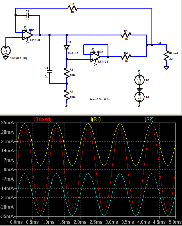
A class-B (typical) opamp that is designed for, say, +-30mA output current will happily provide +-10mA load swing either in class-B (-10mA...+10mA) or in class-A (+5mA...+25mA). Except for the output stage the rest of the internals are usually class-A in most IC opamps, only some micropower specialist types may have class-AB driver stages etc.
Some OpAmps even provide true "class-A" output pins (the comp. pin of the venerable 5534, ie).
@EWorkshop1708: The MC33079 is a "known good" quad audio opamp, and probably the best in price/performance ratio in the bipolar category. 33078's/33079's are used in many upper class hifi and studio gear.
- Klaus
Measurement bias current final stage OPA134
I add a picture with this post, but I doubt whether it will be placed. What I did is measured the current in the positive and negative supply pins of the OPA134. The supply was +10.5V -10.5V. I used a harmonic signal of 200 Hz and 34.6mV effective voltage. The output was shorted with a resistance of 165Ohm.
I visualized the current through the supply pins with an oscilloscope. I increased the signal amplitude till the harmonic current signal in the supply pins begins to look distorted.
The maximal current (amplitude of harmonic current) turns out to be 0.3mA. So I conclude that the bias current in the final stage of the OPA134 is about 0.3 mA.
If you want to know more details, let me know.
Attachments
The actually question must be follow: How much is the DC current (bias) through each stages?Hi everyone, Has anybody came across Class-A opamps?. Do they really exist.
Does there is a way in which a regular class-AB opamp could be converted to Class-A opamp. waiting for replies....... Regards, Kanwar
Most opamp datasheets offer only the whole DC current so as sometimes the spread aera. But most op-amps contain basically two voltage gain stages so as SE/PP-BUF (top quality opamps uses only one voltage gain stage - mostly as folded cascode like AD797 or OPA2604/2134).
I want to know the idle current of each stage.
BTW - each stage of all OP-Amps works always in pure class A (also the output stage), if the used AC/DC output current is below the quiescent current.
The idea from post #72 and #73 is very good (thank you therefore), but I would like it, when the manufacturer-datasheet would be offer accurate data in this matter.
Last edited:
I don't think so.
let's use a simplified example of an opamp that has the 3 stages of the Lin topology and the last stage is push pull.
The first stage draws Quiescent current Iq1
The second stage draws Quiescent current Iq2
The third push pull stage draws Quiescent current Iq3 = Ibias
Let's further assume that no other quiescent current is drawn by auxiliary circuits.
Iq1 & Iq2 could be feeding single ended ClassA stages.
The total quiescent current (Iq) is Iq1+Iq2+Iq3
The maximum ClassA output of the Lin amp is 2*Iq3
We have many combinations of varying current in the 3stages as the output current is increased towards IclassA max.
One must account for Iq1 & Iq2 before one can draw conclusions about IclassA max.
Then the opamp will have a non zero Iauxiliary. More complication
Opaq's method relies on the not unreasonable assumption that the rail currents of a ClassA amplifier follow the ClassA output current.
It appears he has detected the change in rail currents to include the half wave rectified versions of the ClassB output current.
Last edited:
I don't think so.
let's use a simplified example of an opamp that has the 3 stages of the Lin topology and the last stage is push pull.
The first stage draws Quiescent current Iq1
The second stage draws Quiescent current Iq2
The third push pull stage draws Quiescent current Iq3 = Ibias
Let's further assume that no other quiescent current is drawn by auxiliary circuits.
Iq1 & Iq2 could be feeding single ended ClassA stages.
The total quiescent current (Iq) is Iq1+Iq2+Iq3
The maximum ClassA output of the Lin amp is 2*Iq3
We have many combinations of varying current in the 3stages as the output current is increased towards IclassA max.
One must account for Iq1 & Iq2 before one can draw conclusions about IclassA max.
Then the opamp will have a non zero Iauxiliary. More complication
Opaq's method relies on the not unreasonable assumption that the rail currents of a ClassA amplifier follow the ClassA output current.
It appears he has detected the change in rail currents to include the half wave rectified versions of the ClassB output current.
what this refers ?? (post #??)
The term "non zero Iauxiliary" I haven't heard until this day. Sorry for my bad english.
Mean you the necessary base input current value of the follow stage?
This must be much more lower than the quiescent current of the previous stage.
The LM1875 already boils so I'm not sure that's really a good idea with its TO-220 package.
Remember the dissipation in meaningful Class A bias goes up quite a bit due to the squared relationship.
Plus with the LM1875 in particular the protection circuit might not be very happy with what it senses.
Remember the dissipation in meaningful Class A bias goes up quite a bit due to the squared relationship.
Plus with the LM1875 in particular the protection circuit might not be very happy with what it senses.
- Status
- This old topic is closed. If you want to reopen this topic, contact a moderator using the "Report Post" button.
- Home
- Amplifiers
- Solid State
- Class-A Opamps