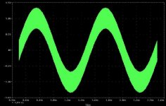
Here is the output signal with a sinusoid 20 dB below clipping. One can clearly see the switching residual sitting on the "payload", as usual for today's switching amps that have less carrier suppression in favour of a better frequency response.
Before someone starts a discussion on this: Bear in mind that this example amp would be capable of 8 Watts approx and that the shown residual would be 6 mW approx.
Before someone starts a discussion on this: Bear in mind that this example amp would be capable of 8 Watts approx and that the shown residual would be 6 mW approx.
Attachments
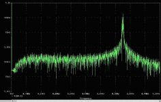
Here one can see the FFT of the same output signal. The artefacts below 10 kHz are more than 90 dB lower than the signal itself.
The switching signal is indeed noise-like with a strong peak around 750 kHz (which can be influenced by the circuit dimensioning of course):
The switching signal is indeed noise-like with a strong peak around 750 kHz (which can be influenced by the circuit dimensioning of course):
Attachments
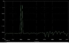
Below is the output spectrum when driven with a 10 kHz and a 11 kHz sinusoid, both 12 dB below clipping (resulting in a peak output signal of half the output voltage capability). Artefacts are well below -80 dB relative to the desired signal.
All in all this principle seems to offer quite astonishing results for a switching amp (even more considered how easily it might be implemented)
I have already mentioned my opinion many times but I will repeat it once again: I by myself I am a fan of switching amplifiers. I am also convinced that they won't beat the best conventional amps available. But they are suitable for much more applications than they are currently used (and I am not talking of LOW FI aplications).
Regards
Charles
Attachments
Lars
Why don't you try to compensate for the output-filter's poles (like I did with the PID) on one of your amps and report us how it performs when feedback is taken from the filter output ?
If you need info on the maths I can help you out.
Lacking of time, I would be among the first ones who would buy DECENT switching amp modules !
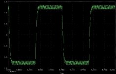
I played around a little more with the circuit and did some runs with rectangular input signals. I didn't use anything to isolate the load from the output and it looked already very good, although for a practical implementation the usual measures would give some peace of mind (not only to avoid unwanted oscillation but also to guarantee the intended one !!!).
There was some overshoot with 2 Ohms, which is in fact 1/3 of the nominal load impedance. From nominal load impedance, up to no load at all, everything looked fine however.
Regards
Charles
Why don't you try to compensate for the output-filter's poles (like I did with the PID) on one of your amps and report us how it performs when feedback is taken from the filter output ?
If you need info on the maths I can help you out.
Lacking of time, I would be among the first ones who would buy DECENT switching amp modules !
I played around a little more with the circuit and did some runs with rectangular input signals. I didn't use anything to isolate the load from the output and it looked already very good, although for a practical implementation the usual measures would give some peace of mind (not only to avoid unwanted oscillation but also to guarantee the intended one !!!).
There was some overshoot with 2 Ohms, which is in fact 1/3 of the nominal load impedance. From nominal load impedance, up to no load at all, everything looked fine however.
Regards
Charles
Charles: Good idea, it turned out that it was really easy to do just that. So i did it.
There are 2 problems, the system becomes vulnarable to high capacitive loads, as the switching frequency is now depending on the load capacitance. At too low switching freq's the loss current in the choke rises to unacceptable levels.
Maybe we can find a way around this.
Another thing is that the real life THD didn't seem to have improved, but is also 0.02% with the new setup. Didn't have too much time to play with it though... Also didn't listen to it.
There are 2 problems, the system becomes vulnarable to high capacitive loads, as the switching frequency is now depending on the load capacitance. At too low switching freq's the loss current in the choke rises to unacceptable levels.
There is only one thing I can say: I S O L A T E the output from the load at high frequencies, like it is done with ordinary amplifiers. This can even act as an additional RF filter.
The disadvantage of the PID is that you can only properly (i.e. mathematically correct, which doesn't mean it wouldn't work in practice OTOH) compensate for filters with a Q up to 0.5 (0.5 is also the easiest variant to calculate BTW).
There are other possibilities to compensate for higher Qs as well but I wouldn't use these circuits, since they need more OP-AMPs which might probably cause more problems than they solve.
Regards
Charles
Charles: You are right, you can compensate for the inherent instabilities in the design, using output chokes etc. but i think it's much healthier to start with an inherent stable system, and then improve on that until the maximum level of quality is reached.
As a fellow DIY'er i fully understand your assumption that the any solution found in the industry (after 100's of hours of work) are totally wrong, and can easily be improved with a couple of hours on the simulator. But not ALWAYS true")
However i really don't find grounds to pursue this suggestion further. It has flaws too, like longer delays in the feedback loop, sensitivity/instability to capacitive loads, and it did not improve on the THD i real life.
So it can qualify as 'another solution', but not the solution to the better amplifier.
Another thing: Stop simulating you guys, build instead!
It's more fun! .. get the ol' soldering iron out of the closet, and do the real thing ..
As a fellow DIY'er i fully understand your assumption that the any solution found in the industry (after 100's of hours of work) are totally wrong, and can easily be improved with a couple of hours on the simulator. But not ALWAYS true
However i really don't find grounds to pursue this suggestion further. It has flaws too, like longer delays in the feedback loop, sensitivity/instability to capacitive loads, and it did not improve on the THD i real life.
So it can qualify as 'another solution', but not the solution to the better amplifier.
Another thing: Stop simulating you guys, build instead!
It's more fun! .. get the ol' soldering iron out of the closet, and do the real thing ..
However i really don't find grounds to pursue this suggestion further. It has flaws too, like longer delays in the feedback loop, sensitivity/instability to capacitive loads, and it did not improve on the THD i real life.
I do of course not assume that all solutions in the industry are wrong. But there is always the possibility that someone comes up with an idea that is actually better. Keep in mind that I experiment with switching amplifiers for about 15 years now. I was even once invited to write an article for a magazine on that subject.
I do furthermore not assume that a simulation represents real-life, but it shows tendencies. And the topology I simulated shows interesting ones.
There are things however, that one cannot easily discard. Even though the measurements, done with your amp, didn't show less THD doesn't that mean that it wouldn't have sonic merits (less load-dependant frequency response for instance, better transient response). And there are always possibilities to make the very same circuit sound/measure better or worse, depending on implementation and dimensioning.
Mathematical analysis shows that your above statement does not necessarily have to be true if the outpout LPF's transfer-function is PROPERLY taken into account. It is even possible to have less overall delay for the amplifier (did you measure that ?). This can be proven mathematically and it must therefore behave like that with some accuracy (which I belive to be quite high, though not 100 % of course).
Regards
Charles
BTW: There are NO amplifiers that are intrinsically stable for ALL load conditions, not even linear ones ! Many commercial switching amplifiers with overall feedback HAVE additional circuitry to improve stability.
Anyone knows how Acoustic Reality manage to get so low distortion from their PWM amps?
How low is it actually ? Sorry, but I am too lazy to find out by myself.
Also has anyone listened to eaRmkII side by side with Zapulse in its latest incarnation?
Maybe Mr. Zapulse himself (Lars) had the opportunity to do so ?!
Maybe tri amp with PWM in lows and mids and good old class A to the tweeter.
That's what is already done. One advantage of "ordinary" amps is their HF response but switching amps are improving on that one as well.
I also had the opportunity to hear a fully active studio monitor that uses switching amps throughout, made by a famous Danish company (and NO it wasn't B&O !!! But Denmark seems to be something like the European driver manufacturer- and switching amp- Mecca anyway).
Keep in mind that the usage in an active system is less demanding and many amps can excel in such an application if used properly.
BTW doesn't the picture below look interesting (the gaps are due to resizeing) ?
Regards
Charles
Attachments
Acoustic Reality is situated about one kilometer from my office, so i have plans to go there one day, and make an afternoon with Peter, who by the way is an old friend of mine.
Charles i agree with you, that each amplifier can be optimized to excel in a specific frequency band, and with an active x-over you can get great results, even if using only PWM amp's. I have done so with a set of Scanspeak Revelator units in a 2-way box, and i was very satisfied with the result.
Charles i agree with you, that each amplifier can be optimized to excel in a specific frequency band, and with an active x-over you can get great results, even if using only PWM amp's. I have done so with a set of Scanspeak Revelator units in a 2-way box, and i was very satisfied with the result.
I have done so with a set of Scanspeak Revelator units in a 2-way box, and i was very satisfied with the result.
Ahhh !!!!!
That's one thing that might be interesting for some people here (maybe even for you
).Regards
Charles
Looks good.BTW doesn't the picture below look interesting (the gaps are due to resizeing) ?
The tweeter amp could be a class D with a high frequency of oscillation. Since less power is needed, lower voltage, higher frequency mosfets could be used.That's what is already done. One advantage of "ordinary" amps is their HF response but switching amps are improving on that one as well
I think the AR amps has about 0.005% at low/medium levels in the mids and bass (slightly rising at the extreme lows). Above 1k or so it raises plenty up to 20k... actually the graphs (performed by Danish High Fidelity) is very similar to the GamuT D200 that a couple of years ago received about the same rave review as the eaR amp.
Pass amps (aleph) seems to have similar (but higher in level) graphs. What separetes the GamuT D200 from the eaRmkII is that it has dominant even order harmonics and totally lower high harmonics (above 5th or so).
I´ve listened to both Aleph 5 and GamuT D200 and they sound wonderful BUT I think the bad high frequency performance can be heard as a slight "veil" and loss of ultimate clarity and "snap" with transient and demanding high frequency sounds.
My references is Zapsolute mkII ULC 78W mono´s and Patriot V100 when it comes to handling complex high freqency sounds.
So, earlier I´ve been searching for something that "has it all" but now I´ve given up that and I´m currently looking for separate amps for an all active system.
The amps that seems to get good reviews all over and also has (what I believe is necessary) the lowest distortion is as far as I know;
eaR (Danish) PWM
GamuT (Danish) High Bias FET
Halcro (Australia/New Zeeland?) ?
Dynamic Precision (Norway) High Bias BJT
Most FET amps seems to have rising THD above 1k but good BJT designs such as LC Audio and Gryphon (Sankens humongous power outputs) seems to be linear up to several octaves/decades above the audio spectrum.
Lars, yes I do believe class A still rules for the top 3-4 octaves at least.
/Peter
Pass amps (aleph) seems to have similar (but higher in level) graphs. What separetes the GamuT D200 from the eaRmkII is that it has dominant even order harmonics and totally lower high harmonics (above 5th or so).
I´ve listened to both Aleph 5 and GamuT D200 and they sound wonderful BUT I think the bad high frequency performance can be heard as a slight "veil" and loss of ultimate clarity and "snap" with transient and demanding high frequency sounds.
My references is Zapsolute mkII ULC 78W mono´s and Patriot V100 when it comes to handling complex high freqency sounds.
So, earlier I´ve been searching for something that "has it all" but now I´ve given up that and I´m currently looking for separate amps for an all active system.
The amps that seems to get good reviews all over and also has (what I believe is necessary) the lowest distortion is as far as I know;
eaR (Danish) PWM
GamuT (Danish) High Bias FET
Halcro (Australia/New Zeeland?) ?
Dynamic Precision (Norway) High Bias BJT
Most FET amps seems to have rising THD above 1k but good BJT designs such as LC Audio and Gryphon (Sankens humongous power outputs) seems to be linear up to several octaves/decades above the audio spectrum.
Lars, yes I do believe class A still rules for the top 3-4 octaves at least
./Peter
I think that the reason is that the gate capacitance factors in more at higher frequencies when used in analog circuits. But that reason should not apply to PWM amps. I do not mean to imply that you thought it wouldMost FET amps seems to have rising THD above 1k
hi.
we use feedback after the output filter in our pwm amps and i think this is part of the reason why they sound very good indeed compared to other switching amps and to good class a/b amps too
it is however demanding on the design and layout of the pcb , this and our extensive use of smd parts makes them less suited for the diy community (imho)
we are looking at this however, if you have suggestions, comments or questions feel free to contact me.
rgds and merry christmas to all -
karsten madsen - www.cadaudio.dk
- Status
- This old topic is closed. If you want to reopen this topic, contact a moderator using the "Report Post" button.
- Home
- Amplifiers
- Class D
- Class A and A/B vs. Class D