I'm guessing Bear, you don't trust cap. output, regardless.
Well, I have been absolutely fooled by cap. coupled outputs. They may show worse on THD at extremes of the frequency response but if you asked whether my fave music sounded better or worse through a 4700 uF cap. with a single rail power supply. I have had to admit on occasion that either "it depends on the rest of the amp design" or "there is a difference but I can't say whether it's going to be better or not, long term."
Most guys who poo-pooh cap. coupling either parrot what the engineers insist or refer to ancient budget amps that were inadequate in more ways than just the AC coupling. I prefer to think that few of us have actually heard a good implementation.
Typicallly 80mH and DCR of around 0R5. This is a BIG, heavy lump. But it can double efficiency to about 30% for a Class A.
Hugh
Interesting idea. I have seen it other times in drawing but never implemented in reality. But, with your numebers, what do you mean, a standing current of (10/0.5) 20A? Do I miss something?
BTW, a most intriguing implementation, without current source, I have seen uses a filament lamp as a (non linear) load. I believe (not sure, really ) was Nelson Pass idea.
Thanks thanong.
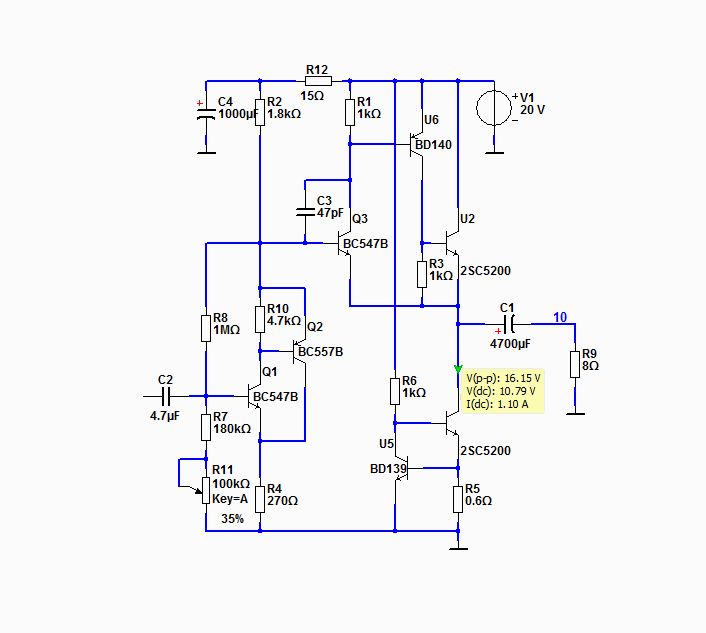
Here is first the simplified idea. See my attached diagram!
Q1 is the voltage amplifier.
The voltage gain is ruffly R1/R5 = 1800/270 ~6.6
After the voltage gain is one buffer follower = U1
The follower is biased by a CCS constant current source = I1
The final circuit uses heavy local feedback and so the distortion is rather low.
The circuit is very easy to setup and try and gives good Class A sound.
I show the complete circuit in my next post.
I am very happy for anyone who try this simple experiment.
It may sound better than you think - with only Class A 4 Watt ...
")
A question about the circuit :
why did you use a CFP arrangement for the output in place of the more common darlington? More local feeback?
Similar reasoning for the input transistor?
It just seems like an interesting way to make the amp DC coupled, when Lineup gets back to this thread I will be interested in his comments.
You can always DC couple and still use a blocking cap too!
The amp is essentially a Nelson Pass Zen but with the output config made more complex, and the input transistors made more complex. The same but different? Ok the Zen had gain in the output, iirc. But still...
Speaking of which the connections of the two input transistors, from whence does that configuration come? I think I have seen it here and there, but quite frankly I find it confusing and am not sure how it works or what its benefits are. (shows blissful ignorance in public)
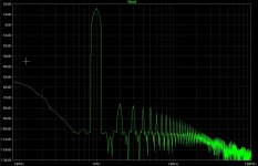
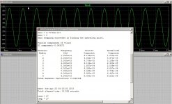
I've been playing with alternate front ends for this output stage since I felt more could be had from it. What I came up with is a bit more complex but keeps with the theme of local feedback and only 2 transistors. I'm not going to post it as to not step on Lineup's toes with his excellent design here, unless he asks me to. That being said the output section is definitely very capable. I will give some teaser sim results. These are at 5 watts into 8 ohms.
Attachments
G'Day
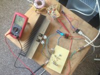
Having just found this thread yesterday, I spent this afternoon building it with parts that I had available it does deserve better though
Let it soak for a couple of hours and then had a listen. This is an excellent sounding amp IMO won't bother you with all that review BS. Takes me back to zen, doz type amps. Running fe168 in MLTL so 4W no worries.
Ran the scope through the frequencies no trouble, 10k sq wave rings a bit but wires would require tidying up, calibrate probes etc will play around with the pF cap only had 10pF to hand. But happy days great design low part count great specs, what's not to like.
Many thanks to Lineup for his design and posting it.
Regards
Bruce
Attachments
Hello lineup!
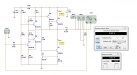
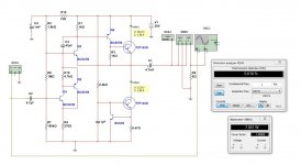
This amplifier very interested and I do two simulations with transistors that I have in my drawers.
I am not a technician and I do not know if will work here, I spent the 30v power supply that provides 7W (805 mv input) and using TIP142 and 2N5886.
What about you?
Thank you!
This amplifier very interested and I do two simulations with transistors that I have in my drawers.
I am not a technician and I do not know if will work here, I spent the 30v power supply that provides 7W (805 mv input) and using TIP142 and 2N5886.
What about you?
Thank you!
Attachments
- Home
- Amplifiers
- Solid State
- Class A, 4 Watt, No Feedback, Simple Circuit, Great Sound