A thought about the fat Thor, I think a deep Thor might be better because it wouldn't make you revise the crossover. As shown by Bjorn's measurements, the design is perfectly flat through the baffle-step region but making the baffle wider would change that. Another bonus, making the cabinet deeper wouldn't make it look any bigger from the front.
catapult said:Another bonus, making the cabinet deeper wouldn't make it look any bigger from the front.
It would have to be a bit taller to accomodate the large cross-section thru the bend -- you might be able to compensate somewhat by exiting the terminus out the top.
Making it deeper was my 1st thot, just for the reason you gave -- no mucking with the XO... it would be almost 2/3 of a metre deep...
dave
Good point, Dave. That might actually work quite well because the tweeter in the stock version is only about 31" above the floor. That's a bit low for an MTM and most listener/chair combos. Moving it up another 5.5" (doubling the cross-section) would be about right for me and my chair.It would have to be a bit taller to accomodate the large cross-section thru the bend
There are also some advantages to having a top-mounted vent (although I'd restrict the area a bit for some mass-loading. Probably). At present, the vent only works on the horizontal room-modes to any great extent, and also, I'm with Lynn Olson on this: if you're going to drive the room's horizontal mode, the vent is best near the floor to get some additional gain there. Placing the vent on the top might increase a bit of ripple, but it would also drive the room's vertical mode very well too, which is very useful - the vertical room mode, tend to sound faster, and cleaner than the horizontal modes.
Best
Scott
Best
Scott
I wonder if some appropriate offset could be added, flip the box over (allowing a floor exit) and still get the drivers at an appropriate height?
quick & nasty -- 0.336 offset from Martin's tables... about 2.05 metre line ... ~690 mm from the bottom of (upside down) box, add 140 for the FatThor, and say another 50 for a stand to allow bottom exit -- 880 mm ~ 35" tweeter height.
dave
quick & nasty -- 0.336 offset from Martin's tables... about 2.05 metre line ... ~690 mm from the bottom of (upside down) box, add 140 for the FatThor, and say another 50 for a stand to allow bottom exit -- 880 mm ~ 35" tweeter height.
dave
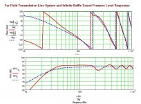
1st pass plans for the "Fat Thor" inspired by this thread. There may be some room for further optimization (ie can it be a bit smaller?)
Twice the cross-section, drivers offset as per MJK tables for a 3:1 taper ratio, terminus out the bottom.
dave
Twice the cross-section, drivers offset as per MJK tables for a 3:1 taper ratio, terminus out the bottom.
dave
Attachments
Okay, after playing around with the dimensions, here's my final offering for these drivers, based on Dave's FatThor:
Line length, geometry and driver positions remain as per the FatThor CAD drawing above.
So = 2.5 Sd (just under actually: 13.5"x7.5"). This will make for a cabinet that's around 3.25" shallower than the FatThor overall, which is useful, though it's never going to be a small cab!
Keep Sm as per Dave's diagram, which is an area of 1Sd. Now, mass-load the cabinet a la Martin's proceedure by installing a 3"x4" (WxL) port near the base of the rear panel (my choice), or on the base itself. Stuffing remains the same as the original Thor at 0.78 lbs to the cubic foot -these drivers in a TL of any type appear to need it, though you can reduce to taste if you don't mind sacrificing an increased level of ripple. As per usual, remember to add 6 db for the paralleled drivers, and remember to take baffle step loss into consideration.
These are big cabinets, but as they're built from MDF (potentially), they should be cheap enough to construct -there's nothing fancy about them, so I'd encourage any existing Thor owners to spend £30 on some more MDF and a couple of ports and rough up a pair of these, or the FatThor cabs I based them on that Dave has drawn. Either would be worth it, of that I'm sure, and both will do justice to these drivers.
Regards
Scott
Attachments
1. Scott - I am not sure I undertand - do you mean an additional port?
2. Scott - Here 30 Pounds will get you a 16mm sheet of MDF. A 22mm Sheet is double the price. This is 1/4 of the average monthly salary in SA so maybe not all that cheap.
3. Planet - Why do you prefer having cabinet open to the floor?
2. Scott - Here 30 Pounds will get you a 16mm sheet of MDF. A 22mm Sheet is double the price. This is 1/4 of the average monthly salary in SA so maybe not all that cheap.
3. Planet - Why do you prefer having cabinet open to the floor?
Byrd said:1. Scott - I am not sure I undertand - do you mean an additional port?
2. Scott - Here 30 Pounds will get you a 16mm sheet of MDF. A 22mm Sheet is double the price. This is 1/4 of the average monthly salary in SA so maybe not all that cheap.
3. Planet - Why do you prefer having cabinet open to the floor?
Sorry if I wasn't clear. No, it means that the end furthest from the drivers is sealed, not open, but has a 3"x4" port in it, or just above. This is the mass-loading technique suggested by Martin -the constricted area and air-mass in the port provides additional loading to the quarter-waves in the cabinet. It's unusual to employ it with a traditional TL geometry, I admit, but not unknown.
Ouch. I didn't know MDF was so expensive over there an 8'x4' 3/4" sheet is circa £10 - £12 in the UK. My apologies. Then again, as these are hardly cheap drivers etc, I assume that few people on the average monthly wage would be able to build Thors? I know I can't afford them (at present...;-)!
I'm with Dave on the low-mounted port / vent. They couple better with the floor and room boundaries than high-mounted vents. It's quite an interesting effect I find: speakers with a vent high up often sound more strained than an otherwise identical design with it mounted lower down. Every little helps. And mounting it as Dave has done in his FatThor means it will drive the rooms vertical resonant mode too, which can give quite a clean and fast boost with fewer of the drawbacks to driving the horizontal mode -there's less in the way for example.
Regards
Scott
Of course that is true, not many people here would be able to afford to build the Thor's.
I guess I am one of those "privileged" white South Africans that I am sure you have all heard / seen reported in the press all these years. I am in fact so overadvantaged that the goverment has seen fit to disallow me ( as a "white" citizen ) from being a part of incentivised investment programs. As a stand against this I have disinvested from South Africa and as a result had a bit of spare cash to fund this project.
I'll test the various configurations that have been suggested though I am not sure that I will be able to measure anything effectivley for you. I will need to be getting some measuring equipment soon. I have heard a Behringer mike being recommended here. Thoughts on this?
So = 2.5 Sd (just under actually: 13.5"x7.5"). This will make for a cabinet that's around 3.25" shallower than the FatThor overall, which is useful, though it's never going to be a small cab!
<...>
Regards
Scott
Planet10, would you adjust your drawings? BTW - what do you use? AutoCAD? Thanks for metric measurements!

Scott, did you change anything in crossover when you generated response chart?
Another questions related to the drivers' position - after moving vent down, and leaving drivers in the same location, sound (air pressure, *shrug* - I'm not professional here, so sorry for the terms) inside the cabinet don't pass through whole stuffing when it goes towards the vent. How does this affect final result?
As well, Scott, does your calculation take such details? as I understand you are writting thesis about those calculations...?
Finally - keep doing good job, guys.. I'm tracking this thread and I'm very curious to see the final result. Never know, maybe I'll build them one day...
Scottmoose said:Line length, geometry and driver positions remain as per the FatThor CAD drawing above.
So = 2.5 Sd (just under actually: 13.5"x7.5"). This will make for a cabinet that's around 3.25" shallower than the FatThor overall, which is useful, though it's never going to be a small cab!
beta 1 attached. To keep the bend consistent, the partition is a bit longer & the box a bit shorter (18mm & 18mm). Once up on pedistals it is going to be even more imposing...
dave
Attachments
jackinnj said:it could be renamed "Falstaff"
A better name would be a good thing, especially if someone is going to build one.
dave
tamosius said:
Scott, did you change anything in crossover when you generated response chart?
Another questions related to the drivers' position - after moving vent down, and leaving drivers in the same location, sound (air pressure, *shrug* - I'm not professional here, so sorry for the terms) inside the cabinet don't pass through whole stuffing when it goes towards the vent. How does this affect final result?
As well, Scott, does your calculation take such details? as I understand you are writting thesis about those calculations...?
My thesis is actually on 20th century naval history, and acoustics used -sonar, range-finding and direction finding etc. You'd be surprised how relevant much of it is to speaker design (no kidding). When it's completed, I'll stick it up on the web if the University lets me.
Crossover is assumed to be the same -it doesn't affect the MathCad response anyway as it only kicks in above the 1Khz limit of these charts. Above that, it's only the drivers that are contributing, the cabinet shouldn't be doing anything other than providing them with a rigid home.
The stuffing is another issue however, and a fair point. It's only really there to damp the higher harmonics -forget that nonsense about fibres moving and affecting the speed of sound etc, so the positioning isn't particularly critical in this respect. It's the driver position / distance from So that's more important. Ultimately, the quarter-waves generated in the cabinet should pass through all the stuffing anyway, so no worries there.
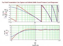
I said the above was my last -well, OK, I couldn't resist. Sorry Dave! Final thoughts: a straight pipe is at last possibly on. So & Sm = 3.5Sd. 45" pipe length. Tweeter centred at 0.35% pipe length from top. Vent is circular and 3"x6" (WxL). Close to a BR box, but not quite -it's still a TL. Stuffing density 0.5lbs to the cubic foot. Stuff from the top to the half-way mark, or just beyond.
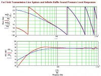
The response is rising slightly below 100Hz -that isn't going to be too much of a problem however, and I doubt boom will be an issue, bacause we'll loose that rise through baffle-step loss. It should be pretty flat overall. And, it's a simple build. I prefer the response of the FatThor variations above frankly (love those drawings Dave, especially that last one!), but this isn't that bad either.
Best
Scott
Attachments
Design comments
Hello Folks:
I though I would offer a few thoughts regarding the construction of these cabinets. The size of the baffles has me a little concerned. I think a significant amount of bracing should be included in the design. I recommend 1/2 in thick plywood that has been drilled out significantly to be mostly holes. I woould put this at the mid point across the front baffle for the top half of the cabinet then repeat it on the bottom half for the front section.
This brace could be easily cut out for the drivers to act as a driver brace as well.
I think Dave knows what I am suggesting, it worked very well on a set of WR125 bipoles I made. Perhaps Dave can comment.
Bracing is really going to be needed the more the better!
I also recommend 1.5 in or so legs off of a slightly oversized base if the bottom vent design is chosen.
I have built with a slight lay back angle, it is a little tricky but definitely worth the effort.
Hope this helps
bacause we'll loose that rise through baffle-step loss.
The original crossover is already compensating for the baffle step as long as you keep the baffle width the same. The Seas anechoic measurement is remarkably flat above 200 Hz and Bjorn's close-mic'd measurement clearly shows the baffle-step compensation. The bass is the only thing that needs to be fixed.
Re: Design comments
Not in the middle!! It needs to be offset enuff that the 1st bending mode is killed instead of enhanced.
I wouldn't have built the thors without adding bracing. This box is bigger.
dave
SCD said:1/2 in thick plywood that has been drilled out significantly to be mostly holes. I woould put this at the mid point across the front baffle
Not in the middle!! It needs to be offset enuff that the 1st bending mode is killed instead of enhanced.
I wouldn't have built the thors without adding bracing. This box is bigger.
dave
- Home
- Loudspeakers
- Multi-Way
- Clarity on Seas Thor Kit