Anyway I well send you later modified schematic for Circlotron Amp with only one Ecc99 and 2x EL34 for your SS BA-3 high gain PreAmp .

ahh, great, thanks

The global feedback will depend on the output impedance of your audio input source. If the source output impedance is close to zero there will be no NFB..
Note to self:
Never let anyone talk you into using feedback loops that include 1st or last stage of amp, unless its for your mother-in-law.
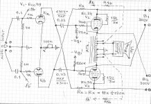
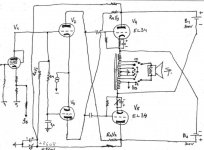
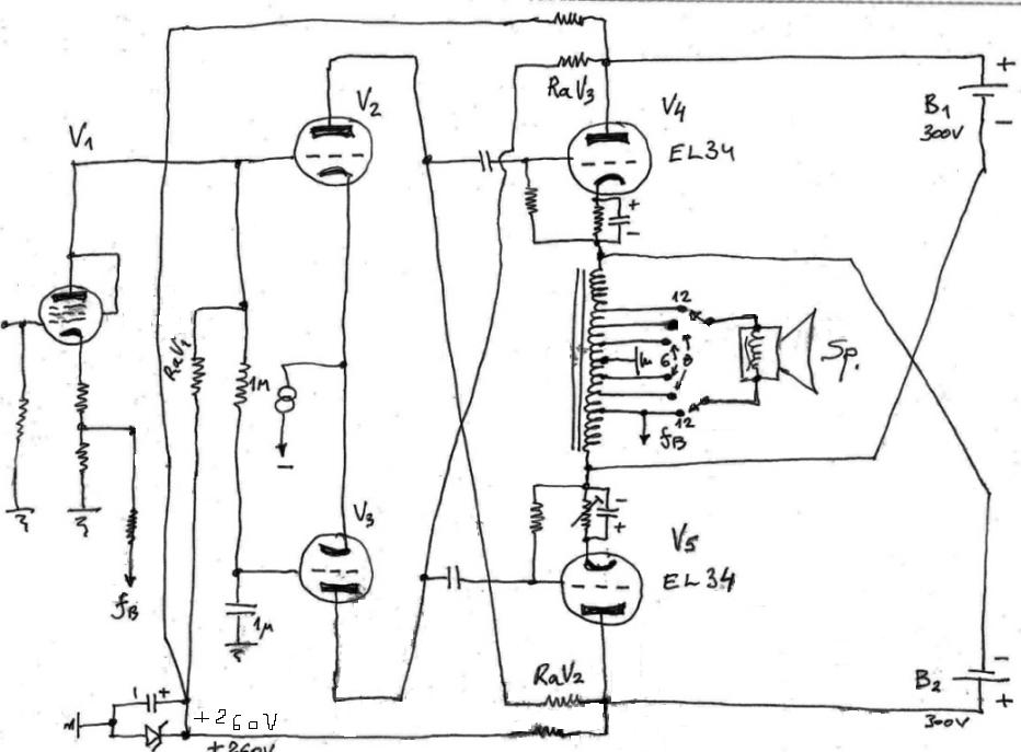
Here is modified schematic :
thanks
NFB...
and there is no way to use either the primary, or one of the other secondaries ?
shoot...I forgot, the two 'balanced' primaries are in series with secondaries
btw, info from another thread indicated that ecc99 wears out fast when driven (or driving) hard
tinitus
Low percent of inserted GNFB ( 2-6 Db ) is just one possible option , normally this type of amp sounds good without any inserted GNFB loop .
If you have some indication that Ecc99 is low quality tube than 12bh7 is good replacement , or 6sn7 , or even Ecc82 , anyway I don`t think that this circuit will be hard working place for Ecc99 tube !
Blumlein garter circuit for input ecc99 tube ? , or some other Blumlein circuit ? can you attach specific schematic please ?
Last edited:
I see now , it is Blumlein garter circuit !
Place to try to insert low percent of negative feedback is to ad third small value resistor (47 - 100 ohm )in series with each upper two cathode resistors to ground , than each feedback loop well be connected in that two node , this solution must be checked by practical probe ,empirical ! , since it is easy to get nasty oscilation beacose Blumlein garter circuit is cross coupled type .
Place to try to insert low percent of negative feedback is to ad third small value resistor (47 - 100 ohm )in series with each upper two cathode resistors to ground , than each feedback loop well be connected in that two node , this solution must be checked by practical probe ,empirical ! , since it is easy to get nasty oscilation beacose Blumlein garter circuit is cross coupled type .
Yes to skip GNFB is OK for Amp sonic , each triode strapped EL34 allready works there with 100% of local NFB .
This circuit works with fixed bias just fine , but to extra increase bias ( anode currents ) is not necessary since Circlotron output power circuit don`t produce crossover distortion almost to very lean class B bias , there is no DC flow present in autoformer coil .
But is very sensitive to unbalanced AC drive , that`s is the reason why I propose differencial driver circuit , diff driver circuit keep AC balance drive almost 100% symmetrically .
For the best sonic results will be Ecc99 diff. driver with inserted CCS instead of 100K trimpot .
Last edited:
But is very sensitive to unbalanced AC drive , that`s is the reason why I propose differencial driver circuit , diff driver circuit keep AC balance drive almost 100% symmetrically.
For the best sonic results will be Ecc99 diff. driver with inserted CCS instead of 100K trimpot .
the ccs have been there, earlier
Attachments
Triode Dick suggests this ccs for the 6n6p
http://www.triodedick.com/monobill_2/monobill_2_schema_versterker.GIF
http://www.triodedick.com/monobill_2/monobill_2_schema_versterker.GIF
The drawback of DC-coupling V1 to V2/V3 is that .........
ups, sorry about that slip
though your input is valid, V1 is gone
well, at least for me it is
and Im not sure that scheme was ever completed
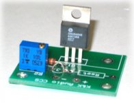
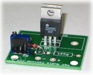
now looking at these ccs 'kits' (K&K)
Attachments
Banat,
Rethink your voltages and gain of each stage. The last proposed will clip at just a few volts out due to clipping of driver stage. The ECC99 will only have an Ua in the of ballpark of 100V at best. I you remove the input stage and drive the ECC99 at0V potential it will maybe give you 20Vptp into 8ohm at a few % THD.
EDIT Haha, Jane our post crossed.
Last edited:
The drawback of DC-coupling V1 to V2/V3 is that this will reduce the plate-cathode voltages of V2/V3. You will lift the cathode voltages (Vk2/Vk3) with the DC from the plate of V1 throw away some precious Vak needed for voltage swing.
Voltage swing is not the problem since driver tube anodes is bootstrapped , connected to opposite EL34 anode .
Best Regards !
Last edited:
Loose the LTP! Go for a PI in the stage before and you can also loose the then unneccesary negative source and CCS. You will also gain 6dB.
The driver stage stage could now be a la Williamsonnd as the origina al PP from Funkschau.
I dont understand

I thought it was pure balanced differential input, and not LTP ?
Hey Banat,
Have you analyzed the swing needed?
Swing from the driver will be a limiting factor with the LTP and DC-connection.
You must take very opportunity you can to maximise it.
Even when bootstrapped and with ECC99 grid referensed to ground the driver will not be far from clipping before the outputstage.
Unfortunately 1,6k Ra-Ra seems to be on the high side and will probably not even give 10W out.
- Status
- This old topic is closed. If you want to reopen this topic, contact a moderator using the "Report Post" button.
- Home
- Amplifiers
- Tubes / Valves
- Circlotron questions