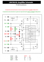
PG+ and PG- are connected at the amp PCB. It's how the circuit board is designed.
Connections from PG- and PG+ go to "power supply caps + and -"... that go to ground!
I am right here? let see the picture here:
Attachments
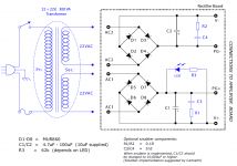
The difference in the two power supplies is that the Audiosector P/S has reversed diode polarity on the AC1 in relation to the AC2.
Electrically they are the same. The Audiosector schematic is drawn a bit non-standard.
Look carefully at thr bridges in #2282 - the lower bridge will charge the lower electrolytic with the WRONG polarity.Electrically they are the same. The Audiosector schematic is drawn a bit non-standard.
Is there a policy here about non-photographic discussions in this thread? Should someone start another thread?
Look carefully at thr bridges in #2282 - the lower bridge will charge the lower electrolytic with the WRONG polarity.
Yes, you are absolutely correct! Good catch!
Where did you get this wrongly drawn sch? I suggest you to remove it, as if build as shown if will probably make explode a 10.000uF capacitor, which is nothing fun for sure!Connections from PG- and PG+ go to "power supply caps + and -"... that go to ground!
I am right here? let see the picture here:
Reg,
which post and which schematic are you referring to?
Post 2282 still being misquoted I think.
Post 2282. Look at the bottom half, positive side of the diode bridge is going to negative side of smooth cap. Negative side is connected to capacitor positive pole.Reg,
which post and which schematic are you referring to?
Safety first, sirs.
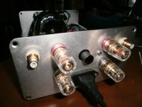
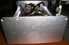
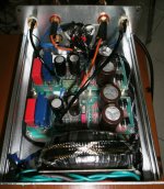
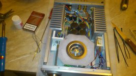
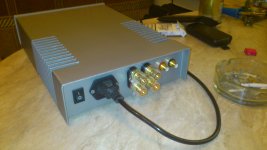
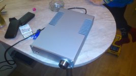
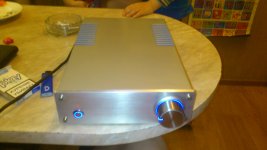
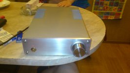
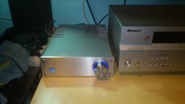
TDA 7293, my first amp
Case - steel, full hand made, front panel - aluminium 5mm, tda 7293
Case - steel, full hand made, front panel - aluminium 5mm, tda 7293
Attachments
- Home
- Amplifiers
- Chip Amps
- Chip Amp Photo Gallery