I also grabbed some special purpose chips for grins and giggles. spectrum analyser chips that are easy for the arduino to interface to. you feed analog into one pin and then clock-out (7 times) some frozen analog values that represent the ampl. level in that bandpass freq band. you need a cpu with a/d (arduino does that) and you just cycle thru the 7 analog values and plot the display on an lcd ")
I plan to have that as an alternate later on.
first problem is: how to best 'sense' the speaker level out and not affect the sound (at all) and also avoid having common grounds on the digital side vs the dual rail voltages that the amp uses. (just cap couple both spkr wires to an op-amp or something high-z?)
has anyone done any work on preprocessing sampled analog levels and following the 300ms VU meter spec? if there is existing code, I'll use it; but if not, I'll write it myself.
spectrum display chip I will later use:
Seven Band Spectrum Analyzer Chip
but not for use with the VU meter project. the spectrum display needs at least a 4x20 lcd display, really.
then again, if you use a bitmap lcd display (not hitachi style) then you could use this chip as a front end, have the cpu process it and send the output as 'summed' data (all 7 bands) to the L and R vu meter graphical widgets OR to some histogram display that keeps that data in the 7 buckets and shows in true histogram format.
I'm not sure I'd like meter widgets when cheap meters that are dc-driven probably look better; but if you plan to use the SA feature you need to do away with meter movements and use a bitmap display instead.
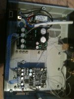
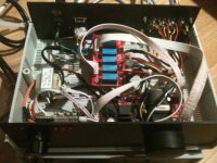
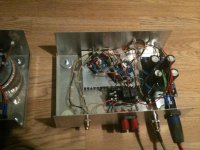
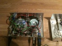
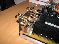
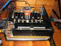
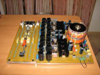
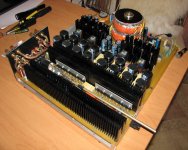
my another gainclone amp,..
have an extra pair of lm1875, then built it with very low cost component
some of them are picked up on broken kitchen ware and computer parts.
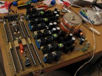
inside look, with real dirty rat nest
have an extra pair of lm1875, then built it with very low cost component
some of them are picked up on broken kitchen ware and computer parts.
An externally hosted image should be here but it was not working when we last tested it.
inside look, with real dirty rat nest
An externally hosted image should be here but it was not working when we last tested it.
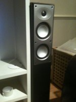
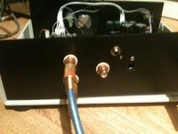
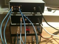
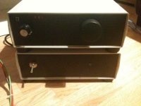
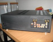
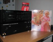
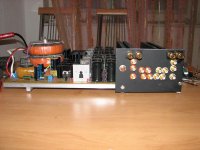
Here is my contribution to this great forum. Ive bitten the audio DIY bug and ive not only assembled a gainclone but also assembled a dac and preamp to go with it. and the sound is phenomenal
Attachments
-
 245 (768x1024).jpg415.9 KB · Views: 2,311
 -
 244 (1024x768).jpg454.1 KB · Views: 2,184
 -
 243 (768x1024).jpg485.3 KB · Views: 2,112
 -
 240 (1024x768).jpg480.6 KB · Views: 387
 -
 241 (1024x768).jpg417.8 KB · Views: 535
 -
 242 (1024x768).jpg505.4 KB · Views: 607
 -
 239 (1024x768).jpg474.1 KB · Views: 328
 -
 236 (1024x768).jpg497.1 KB · Views: 408
 -
 235 (1024x768).jpg515.5 KB · Views: 551
 -
 234 (1024x768).jpg515.3 KB · Views: 557
Heatsinks inside boxes again!!!
Please everybody here!
CPU heatsinks need to be blown by a fan, they are not designed for natural convection cooling.
A heatsink inside a box cannot get rid of heat. The heat MUST be able to escape SOMEHOW!
Heat rises. Don't expect it to crawl out of holes in the bottom of a case.
PLEASE! Spend just 5 minutes reading-up how heatsinks work. Your chips will love you for it!
Frank
my another gainclone amp,..
have an extra pair of lm1875, then built it with very low cost component
some of them are picked up on broken kitchen ware and computer parts.
Please everybody here!
CPU heatsinks need to be blown by a fan, they are not designed for natural convection cooling.
A heatsink inside a box cannot get rid of heat. The heat MUST be able to escape SOMEHOW!
Heat rises. Don't expect it to crawl out of holes in the bottom of a case.
PLEASE! Spend just 5 minutes reading-up how heatsinks work. Your chips will love you for it!
Frank
Last edited:
at least two Forum Members are awake !Spend just 5 minutes reading-up how heatsinks work. Your chips will love you for it!
Well, not really them all. I run one of these without a fan, ok there's a fan on the front panel but it is more than 10 inches away, and because it's running at about 5v the effect is more of a convection designed system.Please everybody here!
CPU heatsinks need to be blown by a fan, they are not designed for natural convection cooling.
Thermalright HR-02 Passive Heatsink Preview
This paired with a good noise-isolating case makes a very convenient PC for audio playback.
You have to put your ear next to the case in order to notice that the computer is ON. I have to do that way because I disconnected the front LEDs (I left it on while sleeping, it's placed 1m away from the bed. Light can be disturbing, noise is not existant
)Of course this works better with 2-core processors (not quads) and low-consumption versions (pretty much lower heat). Today's processors underclock themselves while having light loads (like playing music), so they still run pretty cool.
Regards,
Regi
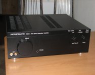
Prophetmaster's Class A Integrated Amplifier
Prophetmaster's 20 W / 4 Hom Class A Integrated Amplifier with 41xBUF634T output
Already placed here photos without the case, now - it is completely ready
Prophetmaster's 20 W / 4 Hom Class A Integrated Amplifier with 41xBUF634T output
Already placed here photos without the case, now - it is completely ready
Attachments
How does it sounds? I planned a similar idea some months ago.
Just one thing, I don't think this is really class A at 20W. This is 40W with 2 channels. A Nelson Pass' F5 provides a near number, 27W per channel, and you really need like 20x times the amount of heatsinks you have.
What amount is the bias?
Regards,
Regi
Just one thing, I don't think this is really class A at 20W. This is 40W with 2 channels. A Nelson Pass' F5 provides a near number, 27W per channel, and you really need like 20x times the amount of heatsinks you have.
What amount is the bias?
Regards,
Regi
How does it sounds? I planned a similar idea some months ago.
Just one thing, I don't think this is really class A at 20W. This is 40W with 2 channels. A Nelson Pass' F5 provides a near number, 27W per channel, and you really need like 20x times the amount of heatsinks you have.
What amount is the bias?
Regards,
Regi
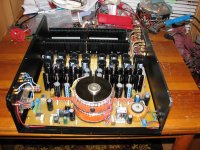
This amplifier has transited already many tests - responses very good.
You are right - for 4 Ohm really class A - up to 11.5 W output, 8 Ohm - up to the maximum output (10 W)
Power consumption: 75 W without a signal
Current without a signal:+/-850 мА
The maximum current in loading (class A) - 1.7 А
Maximum output current - 10 A (Long-time), 16 A (short-term)
Foto from last tests
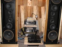
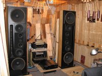
CD Mark Levinson, Speakers Montana WAS. It's U. Makarov audiosystem, Moscow. Its system and monster-amplifiers by which it does, are known in Russia and far outside of Russia.Attachments
Last edited:
Rep
Too sad that this forum does not have a Reputation Point System, like the other forum I'm in. I'd have certainly "Repped" you for your fine work!
Earlier photos
Too sad that this forum does not have a Reputation Point System, like the other forum I'm in. I'd have certainly "Repped" you for your fine work!
Thank You very much for your high opinionToo sad that this forum does not have a Reputation Point System, like the other forum I'm in. I'd have certainly "Repped" you for your fine work!
 It's very pleasure for me!
Prophetmaster what a great work! Congrats!
Just a question, I'm confused. There isn't any problem by fitting those toroids like that?
I thought that wasn't allowed one over the other. Well, aparently there's no problem as you already tested and said it works great, I'm just asking if there's a minimum distance allowed between them or not, due to magnetic fields, etc.
Nice work, and merry christmas to you all.
Just a question, I'm confused. There isn't any problem by fitting those toroids like that?
I thought that wasn't allowed one over the other. Well, aparently there's no problem
as you already tested and said it works great, I'm just asking if there's a minimum distance allowed between them or not, due to magnetic fields, etc.Nice work, and merry christmas to you all.
Prophetmaster what a great work! Congrats!
Just a question, I'm confused. There isn't any problem by fitting those toroids like that?
I thought that wasn't allowed one over the other. Well, aparently there's no problem
Nice work, and merry christmas to you all.
Thank you very much!
There is no problem by fitting those toroids like that!
The minimum distance isn't impotant. The spacer from rubber of 2-3 mm between the toroids is necessary.
Merry christmas to you all too

Prophetmaster what a great work! Congrats!
Just a question, I'm confused. There isn't any problem by fitting those toroids like that?
I thought that wasn't allowed one over the other. Well, aparently there's no problem
Nice work, and merry christmas to you all.
I had a JRDG Model 2 that had both toriods mounted in an aluminum cylinder.. It worked well but I don't know if there was a metal barrier in between them.
You can just barely see it here:
http://www.jeffrowland.com/img/M2-front.jpg
Stacked toroids
Here's a thread discussing stacked toroids:
Consensus is that it's OK with a small spacer between them.
Here's a thread discussing stacked toroids:
Consensus is that it's OK with a small spacer between them.
Thanks Scratchy.. that helps!
And thank you Prophetmaster and troystg for your answer!
Now I get it!
Isn't present for what to thank
. I wish your good luck in creativity!- Home
- Amplifiers
- Chip Amps
- Chip Amp Photo Gallery