Hi Jeanie. The original build had a slight hum. The new build does not. I never found out what caused the hum. I suspect it may have been ground wires too close to the transformer. input wires were not shielded in the original, either. Now they are.
Attachments
TDA 1519AQ
My finished product...made of essentially scrap parts...note the CD board.
Does someone know, does the pin eight, the mute, is it normally open to disengage the mute function?.....because it is not connected, I have no output.
_____________________________________________________Rick.......
My finished product...made of essentially scrap parts...note the CD board.
Does someone know, does the pin eight, the mute, is it normally open to disengage the mute function?.....because it is not connected, I have no output.
_____________________________________________________Rick.......
Attachments
Mute
Hi - my tda7294 wouldn't work either then I realised that the mute was not turned off (on). On the 7294 there is a spec for the voltage level on mute pin for turn on. As soon as I applied 3.5 volts the amp worked. On my PC board I needed to install Berg pins then short two of them together. I could have simply used a scrap piece of wire.
Hi - my tda7294 wouldn't work either then I realised that the mute was not turned off (on). On the 7294 there is a spec for the voltage level on mute pin for turn on. As soon as I applied 3.5 volts the amp worked. On my PC board I needed to install Berg pins then short two of them together. I could have simply used a scrap piece of wire.
So far, extremely quiet!, mute...
Hi there Jeanie, that's what I was afraid of...the schematics I've found show the obligatory spst switch in the open position...& of course I assumed this is the default, disengaged state.
I'll get in there and apply a jumper....wish me luck.
.......Rick.....
Hi there Jeanie, that's what I was afraid of...the schematics I've found show the obligatory spst switch in the open position...& of course I assumed this is the default, disengaged state.
I'll get in there and apply a jumper....wish me luck.
.......Rick.....
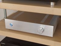
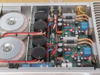

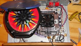
Some pics of my LM3886 composite amp I finished last year.
.
whoah
CPU cooling blocks
Some pics of my LM3886 composite amp I finished last year.
Some of the best workmanship I've ever seen. Beautiful job.
Is it possible to share more details? Maybe in a new thread?
I'm curious about the function of the PC board with the blue transformer that is attached to the inside front panel.
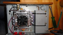
Thanks. To be honest electronics design is my main profession and fine mechanics a secondary. However I build this completely at home as a fun project. Just in my own workshop by hand with regular hand tools and an electric hand drill + drill stand. Only for bending the heat pipes I borrowed a special bending tool from a friend. Casing did come ready made (to some extend) from Ebay.
The PCB in front is the PSU control. It is the click-on-click-off and remote power control to power it on/off from my pre-amp. It also has the inrush current limiter, dc protection and over temperature protection. With 2x 120VA transformers inrush limiting isn't strictly necessary but it avoids the switch on "humpf" and less aggressively charges the buffer caps at power on.
Heat pipes can have the habit (but not necessarily do) to degrade after 10 - 20 years. So I added thermal cut-off's for safety.
Power is 80W rms_sine into 4 ohms and 55W into 8 ohms before clipping. More than sufficient for regular listening. My speakers are 6 ohms mostly.
Last edited:
Noise solution
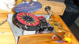
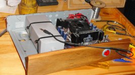
After moving power leads and rotating the transformer the noise abated dramatically. I also relocated the input leads. As quiet now as I would expect, I'm very pleased with the BTL TDA7294 performance and quiescent noise level. The board on the front of the enclosure is a piece of Jarrah, indigenous hardwood to Australia, which covers holes from a previous project. Enclosures are very expensive in Western Australia, shipping parts from the U.S. is also prohibitive. Good used heatsinks are not available.
After moving power leads and rotating the transformer the noise abated dramatically. I also relocated the input leads. As quiet now as I would expect, I'm very pleased with the BTL TDA7294 performance and quiescent noise level. The board on the front of the enclosure is a piece of Jarrah, indigenous hardwood to Australia, which covers holes from a previous project. Enclosures are very expensive in Western Australia, shipping parts from the U.S. is also prohibitive. Good used heatsinks are not available.
Last edited:
After moving power leads and rotating the transformer the noise abated dramatically. I also relocated the input leads. As quiet now as I would expect, I'm very pleased with the BTL TDA7294 performance and quiescent noise level. The board on the front of the enclosure is a piece of Jarrah, indigenous hardwood to Australia, which covers holes from a previous project. Enclosures are very expensive in Western Australia, shipping parts from the U.S. is also prohibitive. Good used heatsinks are not available.
Can you post an updated picture? curious to see the difference.
Vin
Vinster - my pleasure to get some photos together. Current flow generates an electromagnetic field, the current being supplied to the transformer from the 115 or 220VAC outlet is time varying (60 cycles/sec) and the electromagnetic field is the source of hum in most instances. A toroid transformer is designed to minimise radiated electromagnetic energy, for this reason assumption is the input wires are causing problems. A good test is to short the input terminals of your amplifier, leaving it turned on and connected to your speakers. Then you will hear the 50 or 60 cycle hum from your speakers. I prefer zero hum, realistically a small amount of hum is masked and not so intolerable. If you have an oscilloscope you may set the proble to AC coupled and turn the sensitivity to maximum, then attach the probe to the output of the power supply, you will see the ripple there. So there are several sources of hum, radiated stray EM fields and conducted hum from the power supply filtering. It's not practical to have zero 50 or 60 cycle contribution, however, the least is most desirable. More later with photos.
It's obvious with the preamp powered up you will have the hum contribution from that amplified by your amplifier, for that reason this simple test requires just the amplifier connected to the speakers. I'm conducting this experiment now, with the preamp on, there's hum with the preamp volume control set to minimum, then I turn off the preamp and there is till a hum coming from the speakers, especially when I put my ear close to the speakers. When I move 10 feet away the hum is still discernible but not obvious. With the preamp powered up the hum is noticeable even when 10 feet away. A transistor generates noise when it is turned on. There is random motion of holes in the semiconductor matrix, this noise increases when the temperature increases. If you could cool the transistor to cryogenic temperatures the noise also decreases in proportion to e-kt. It's important to establish that zero noise is not practical.
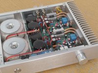
post2978Here's my chip amp build. It has plenty of power, using 300VA power supply with 8,000 uF supply capacitors in C-R-C configuration. Displeased with level of hum which is masked with high volume levels. These 7294's are very noisy! Any suggestions how to lower noise?
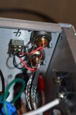
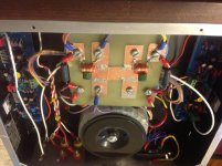
I see 4 wires coming from the centre "H" of the PSU smoothing caps.
That looks wrong to me.
The INPUT pair to the PSU comes from the transformer secondary.
The OUTPUT pair goes to the amplifier/s. The inputs and outputs must remain as close coupled pairs for the whole route from transformer core to amplifier PCB.
Deviating from this creates avoidable interference.
You seem to have an input and an output from one limb of the "H".
and a second input and output at the other "H" limb.
Last edited:
The "H" input/output bus structure flows from bridge rectifiers on the legs closest to the xformer, one leg minus, one leg positive. The center section is the "star ground". As the current flows into the first filter capacitor, pos and neg, then that is connected to the next filter capacitor through a 0.5 ohm 5watt resistor. The second filter capacitor (pos and neg) are distal to the xformer and from the output of that capacitor the flying leads wrap underneath the FR4 and loops around to the voltage inputs?
More photos
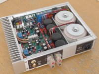
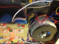
Maybe this photo will serve to clarify, the diodes are black as is the bottom of the enclosure. The negative is Yellow and the positive is Orange, 16 gauge tinned, stranded, high temperature wire. As previously mentioned, before moving the transformer and signal input cables there was a lot of 50Hz hum, I twisted (rotated) the transformer which pulled the xformer output cables tight against the toroid instead of looping? I made certain to keep any signal input as far away from the transformer as possible, following the square law of EM radiation.
Maybe this photo will serve to clarify, the diodes are black as is the bottom of the enclosure. The negative is Yellow and the positive is Orange, 16 gauge tinned, stranded, high temperature wire. As previously mentioned, before moving the transformer and signal input cables there was a lot of 50Hz hum, I twisted (rotated) the transformer which pulled the xformer output cables tight against the toroid instead of looping? I made certain to keep any signal input as far away from the transformer as possible, following the square law of EM radiation.
Attachments
Last edited:
It's your "star ground" that is wired incorrectly.The "H" input/output bus structure flows from bridge rectifiers on the legs closest to the xformer, one leg minus, one leg positive. The center section is the "star ground". As the current flows into the first filter capacitor, pos and neg, then that is connected to the next filter capacitor through a 0.5 ohm 5watt resistor. The second filter capacitor (pos and neg) are distal to the xformer and from the output of that capacitor the flying leads wrap underneath the FR4 and loops around to the voltage inputs?
The wires from the transformer to the rectifier/s MUST be close coupled pairs.
The wires from the rectifier/s to the smoothing capacitors MUST be close coupled pairs.
The wires from the smoothing capacitors to the amplifier MUST be close coupled pairs.
Even better if the close coupled pairs are twisted pairs.
Taking single wires (that pass a varying current) to a star ground increases interference inside your amplifier.
Last edited:
Thanks Andrew, that's useful information which I'll use that in the future. I know you are very knowledgable I previously have seen your posts. My belief is problems associated with hum and noise are paramount in any design. Permit me to add thermal management is also given short shrift. If you are able to eliminate noise and dissipate heat then you are ahead of the crowd.
Last edited:
- Home
- Amplifiers
- Chip Amps
- Chip Amp Photo Gallery