Hey everybody, this is my first post here, as I have known about the forum for a long time, but just recently joined. I have built a few amps over the years, and wanted to share my most recent build, which was done for a family member. A full collection of photos from the entire build are in one of my Flickr albums - https://www.flickr.com/photos/tesladude19/albums/72157661955974493
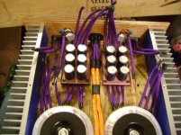
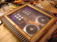
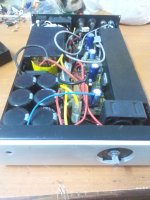
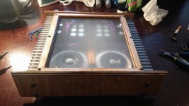
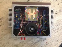
Its technically unfinished.. as I dont have the actual amp boards in yet (I threw my old ones in to test fit everything in the case, as can be seen in the last photo) but I should be getting the new boards for this amp in a few days.
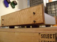
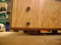
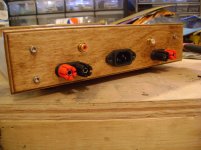
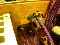
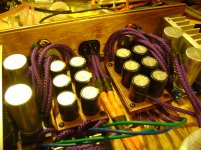
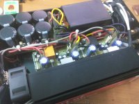
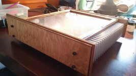
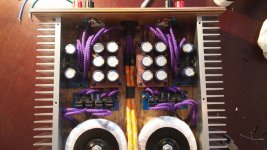
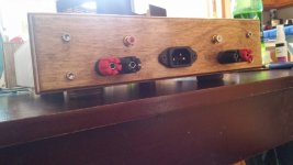
The case is made from plywood, and the heatsinks make up the sides. All wood pieces are stained Early American, except for the boards that hold the capacitors, those are Black Cherry. I used lacquer to give the wood a real smooth finish, and I am rather impressed with how well it turned out.
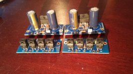
Parts used/will be used - Antek 50VA 20V transformers, 10" profile 2" height heatsinks from HeatsinkUSA, AudioSector LM3875 PCBs, Panasonic FC series electrolytic caps, Vishay BC film caps (except for the 470pF in the low pass filter on the input, that's Kemet), Murata ceramic caps, Vishay Dale 1% resistors, Vishay BC 1% resistors, NXP diodes, 300V rated 22 gauge wire sleeved in paracord.
Enough of me rambling on.. here are some pictures:
Its technically unfinished.. as I dont have the actual amp boards in yet (I threw my old ones in to test fit everything in the case, as can be seen in the last photo) but I should be getting the new boards for this amp in a few days.
The case is made from plywood, and the heatsinks make up the sides. All wood pieces are stained Early American, except for the boards that hold the capacitors, those are Black Cherry. I used lacquer to give the wood a real smooth finish, and I am rather impressed with how well it turned out.
Parts used/will be used - Antek 50VA 20V transformers, 10" profile 2" height heatsinks from HeatsinkUSA, AudioSector LM3875 PCBs, Panasonic FC series electrolytic caps, Vishay BC film caps (except for the 470pF in the low pass filter on the input, that's Kemet), Murata ceramic caps, Vishay Dale 1% resistors, Vishay BC 1% resistors, NXP diodes, 300V rated 22 gauge wire sleeved in paracord.
Enough of me rambling on.. here are some pictures:
Attachments
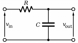
I use a 47pF at the input socket. That capacitance only becomes a filter in association with some preceding impedance.
The interconnect cable has both resistance and inductance. There's the filter.
This filter attenuates external interference as the cable enters the enclosure.
The internal cable potentially picks up interference on it's route across the emi field contaminated space from socket to receiver. I fit the main filter at the receiver to attenuate all the interference. This is where I fit the R+C. This R+C defines the upper limit passband of the receiver. I also fit the lower limit passband filter here.
Last edited:
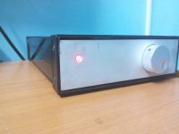
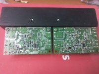
mighty mini build TDA7293 putting out a modest 30W in the smallist chassis .....took me more than 3 month to complete , but the end results were worth it ......
Attachments
-
 IMG_20160216_211736.jpg252.2 KB · Views: 370
 -
 IMG_20160216_195426.jpg287.4 KB · Views: 382
 -
 IMG_20160216_195350.jpg269 KB · Views: 421
 -
 IMG_20160214_110738.jpg293.8 KB · Views: 471
 -
 IMG_20160216_195259.jpg303.5 KB · Views: 353
 -
 IMG_20160214_122158.jpg337.5 KB · Views: 329
 -
 IMG_20160214_122144.jpg288.8 KB · Views: 352
 -
 IMG_20160116_202004.jpg271.8 KB · Views: 458
 -
 IMG_20160214_122110.jpg292.4 KB · Views: 443
Gain Cube
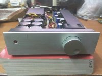
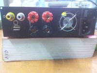
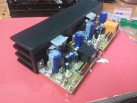
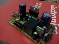
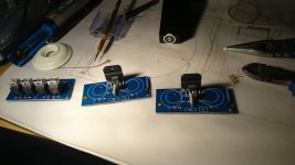
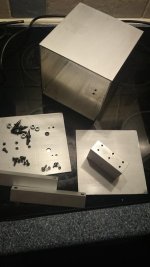
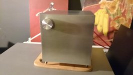
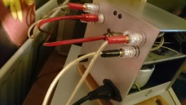
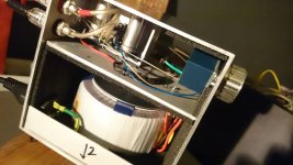
My latest bodge-up. Its an Audiosector LM3875 kit built into a 15x15x15cm aluminium extrusion costing a mere £8.25 which was the cheapest, nicest "different" enclosure I could make using the tools I have...it was bloody hard work squeezing it in without resorting to terminal blocks. The chips are mounted on a 2x1inch (apols for mixing my units but it's how they sold it) solid extrusion to take care of the heat. Sounds good to me and looks good to Mrs.Tonga (a very important consideration).
Apologies if the pictures are too big - I haven't worked out how to do the thumbnail thing.
Ben.
Attachments
Last edited by a moderator:
Finished the amplifier today, and it has turned out better than I hoped for.
Not a single hiss or buzz even with my ears right up to the drivers.
Not a single hiss or buzz even with my ears right up to the drivers.
Attachments
How many mVac of Hum, Buzz and Hiss did your ear next to the speaker tell you was being emitted by your amplifier?Finished the amplifier today, and it has turned out better than I hoped for.
Not a single hiss or buzz even with my ears right up to the drivers.
What does that matter if the OP is happy with the end result???How many mVac of Hum, Buzz and Hiss did your ear next to the speaker tell you was being emitted by your amplifier?
I haven't worked out how to do the thumbnail thing.
 You need to. Those were way too big. I fixed them. Please see here.
http://www.diyaudio.com/forums/everything-else/183084-pictures-why-not-attach-them.html
Provides useful information for other Builders.What does that matter if the OP is happy with the end result???
On this Forum we share experiences.
"I hear nothing" tells nobody anything useful.
I will be able to provide more information at a later date, as I am currently in the process of moving my electronics lab.. and therefore have almost everything packed away. I only have a cheap multimeter available to me at the moment, so I am unable to actually measure anything with any sort of accuracy.
http://www.diyaudio.com/forums/everything-else/183084-pictures-why-not-attach-them.html
Thanks Pano
I was looking for how to do this in the FAQ but couldn't find it.I use Ifanview.
It allows you to crop a pic and/or ro resize a pic and/or to export a pic.
A half a million other things I have not learned to do.
I saw a few recommendations for Irfanveiw so I'll grab that I think. Thanks for the advice Andrew.
TDA7294, BTL mode, stereo amplifier
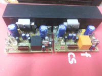
Here's my chip amp build. It has plenty of power, using 300VA power supply with 8,000 uF supply capacitors in C-R-C configuration. Displeased with level of hum which is masked with high volume levels. These 7294's are very noisy! Any suggestions how to lower noise?
Here's my chip amp build. It has plenty of power, using 300VA power supply with 8,000 uF supply capacitors in C-R-C configuration. Displeased with level of hum which is masked with high volume levels. These 7294's are very noisy! Any suggestions how to lower noise?
Attachments
Frustrating, but DONE!
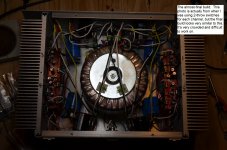
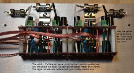
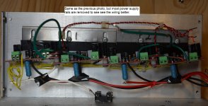
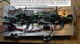
Introducing – not a new build, but a rebuild. Several years ago, I had the opportunity to buy a bunch of LM3886’s and Chipamp.com boards and a huge transformer really cheap. I realized that by putting 2 Chipamp.com boards in parallel, I could build exactly the PA100 described in Texas Instruments’ data sheet SNAA021B.
So I built a 4-channel PA100, using 8 LM3886’s and boards and 4 Chipamp.com power supplies. I posted it here: http://www.diyaudio.com/forums/chip-amps/79303-chip-amp-photo-gallery-220.html#post3132645 Well, it was a bit of a mess, and didn’t sound very good. All 4 channels had a faint hum which I just couldn’t get rid of. So I tore the whole thing apart and rebuilt it. Changes include:
· Parallel boards were moved from side-by-side to one-above-the-other.
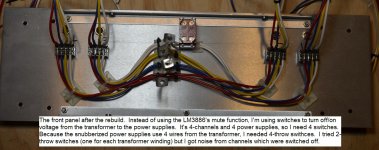
· The mute circuit is no longer used.
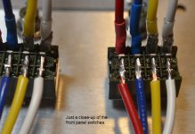
· To turn individual channels on/off I use switches placed between the transformer and the power supplies.
· I’m using a copper braid to shield the signal wires.
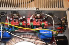
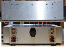
While it works, and the hum is gone, it was really a lot more difficult – and more work – than I bargained for. The amp is over-crowded and has too many wires inside. It’s extremely difficult to get tools, fingers and probes in there to work on anything. Wiring two boards – designed for single chips - in parallel requires creative soldering techniques which really should not be used. Despite diligently testing each part before assembling the whole thing, I had to take the completed amplifier apart twice, because it didn’t work once assembled. By the time I was done, this project was no fun! It’s done now, and I’m going to take a little break from electronics. I’m going to build some wood CD shelves.
Introducing – not a new build, but a rebuild. Several years ago, I had the opportunity to buy a bunch of LM3886’s and Chipamp.com boards and a huge transformer really cheap. I realized that by putting 2 Chipamp.com boards in parallel, I could build exactly the PA100 described in Texas Instruments’ data sheet SNAA021B.
So I built a 4-channel PA100, using 8 LM3886’s and boards and 4 Chipamp.com power supplies. I posted it here: http://www.diyaudio.com/forums/chip-amps/79303-chip-amp-photo-gallery-220.html#post3132645 Well, it was a bit of a mess, and didn’t sound very good. All 4 channels had a faint hum which I just couldn’t get rid of. So I tore the whole thing apart and rebuilt it. Changes include:
· Parallel boards were moved from side-by-side to one-above-the-other.
· The mute circuit is no longer used.
· To turn individual channels on/off I use switches placed between the transformer and the power supplies.
· I’m using a copper braid to shield the signal wires.
While it works, and the hum is gone, it was really a lot more difficult – and more work – than I bargained for. The amp is over-crowded and has too many wires inside. It’s extremely difficult to get tools, fingers and probes in there to work on anything. Wiring two boards – designed for single chips - in parallel requires creative soldering techniques which really should not be used. Despite diligently testing each part before assembling the whole thing, I had to take the completed amplifier apart twice, because it didn’t work once assembled. By the time I was done, this project was no fun! It’s done now, and I’m going to take a little break from electronics. I’m going to build some wood CD shelves.
Attachments
-
 whole amplifier - after.jpg351.1 KB · Views: 455
 -
 front panel - after close up.jpg164.8 KB · Views: 415
 -
 front panel - after.jpg278.7 KB · Views: 474
 -
 after - insides closeup.jpg383.4 KB · Views: 1,117
 -
 heat sink - after.jpg314.9 KB · Views: 1,105
 -
 heat sink - before 2.jpg311.5 KB · Views: 1,137
 -
 heat sink - before.jpg360.5 KB · Views: 1,238
 -
 after - front&back.jpg295.1 KB · Views: 440
Great
Thanks Byron, I'm suspicious of the BTL configuration as a contributor to the hum? It's crowded in this chassis, the input cable is quality and nicely shielded? I have a number of DIY amps... My quietest and therefore, favourite are my Universal Tiger .01's, using "EL" transformers supplied with the kit 40+ years ago. I upgraded the output transistors and installed fresh capacitors (the new small footprint style), I can't tell if it is on without program material. My F5 also has a slight hum, nothing like the TDA7294. Maybe it isn't fair to expect a zero noise floor? With program material the noise is gone, could this be being generated by on chip resistor structures, i.e., thermal, e-kt? The oscilloscope will be brought out and I'll check for the obvious. I have F5 turbo boards on my desk with a pair of toroidal xformers.
Thanks Byron, I'm suspicious of the BTL configuration as a contributor to the hum? It's crowded in this chassis, the input cable is quality and nicely shielded? I have a number of DIY amps... My quietest and therefore, favourite are my Universal Tiger .01's, using "EL" transformers supplied with the kit 40+ years ago. I upgraded the output transistors and installed fresh capacitors (the new small footprint style), I can't tell if it is on without program material. My F5 also has a slight hum, nothing like the TDA7294. Maybe it isn't fair to expect a zero noise floor? With program material the noise is gone, could this be being generated by on chip resistor structures, i.e., thermal, e-kt? The oscilloscope will be brought out and I'll check for the obvious. I have F5 turbo boards on my desk with a pair of toroidal xformers.
- Home
- Amplifiers
- Chip Amps
- Chip Amp Photo Gallery